Roughness detecting method for combined surface of concrete prefabricated part

A technology of prefabricated components and detection methods, applied in the direction of measuring devices, instruments, etc., can solve the problem that the sand filling method cannot be applied to non-horizontal surfaces, and achieve the effect of increasing speed and stable and accurate data

Active Publication Date: 2018-01-23
GUANGZHOU INSTITUTE OF BUILDING SCIENCE CO LTD
View PDF7 Cites 10 Cited by
  • Summary
  • Abstract
  • Description
  • Claims
  • Application Information

AI Technical Summary

Problems solved by technology

[0005] In order to overcome the shortcoming that the sand filling method cannot be applied to non-horizontal surfaces, the purpose of the present invention is to provide

Method used


Image

  • Roughness detecting method for combined surface of concrete prefabricated part
  • Roughness detecting method for combined surface of concrete prefabricated part
  • Roughness detecting method for combined surface of concrete prefabricated part

Examples


Embodiment 1

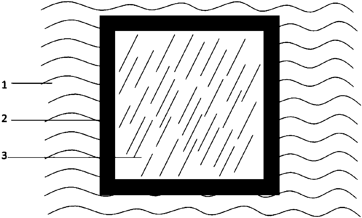
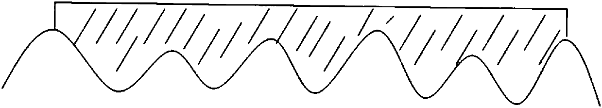
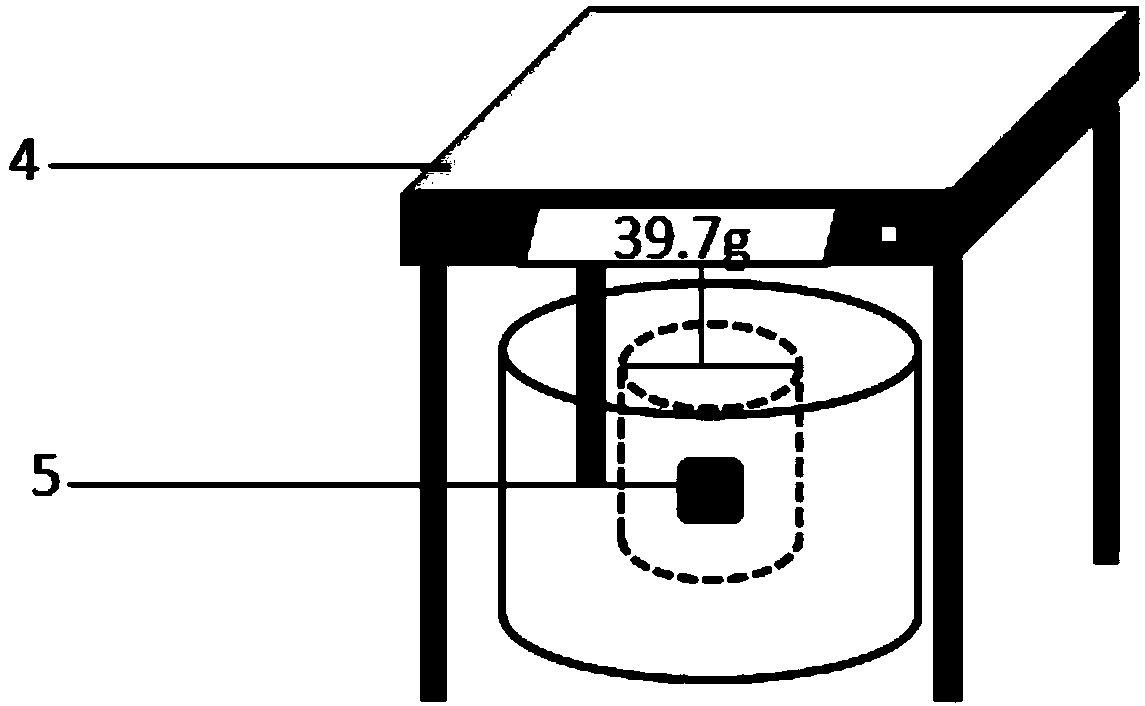
[0035] Randomly select 10 areas on the joint surface of a concrete component, apply a layer of release oil to the selected area, and fix the stainless steel frame in this area; fill the stainless steel frame with plasticine until it is flush with the surface of the frame In this process, it can be squeezed by hand to ensure that the unevenness of the surface of the component is filled with plasticine, and the excess plasticine is removed with a spatula; remove the stainless steel frame, remove the plasticine attached to the surface of the component, and use a hydrostatic balance 4 its weight in air m 1 , accurate to 0.01g, then put the plasticine in the basket and put them in distilled water together, and weigh the mass of the plasticine in water with a hydrostatic balance 4 m 2 Accurate to 0.01g. The obtained data and results are shown in Table 1 below:

[0036] Table 1 uses plasticine to test the surface roughness of concrete (mm)

[0037]

[0038] It can be seen from ...

Embodiment 2

[0040] Randomly select 10 areas on the joint surface of a concrete component, apply a layer of release oil to the selected area, and fix the stainless steel frame in this area; fill the stainless steel frame with plasticine until it is flush with the surface of the frame In this process, it can be squeezed by hand to ensure that the unevenness of the surface of the component is filled with plasticine, and the excess plasticine is removed with a spatula; remove the stainless steel frame, remove the plasticine attached to the surface of the component, and use a hydrostatic balance 4 its weight in air m 1 , accurate to 0.01g, then put the plasticine in the basket and put them in distilled water together, and weigh the mass of the plasticine in water with a hydrostatic balance 4 m 2 Accurate to 0.01g. The obtained data and results are shown in Table 2 below:

[0041] Table 2 uses plasticine to test the surface roughness of concrete (mm)

[0042]

[0043] It can be seen from ...


PUM


Abstract

The present invention discloses a roughness detecting method for the combined surface of a concrete prefabricated part. The method comprises the following steps of 1) cleaning sundries on the surfaceof a to-be-measured part before the test, selecting a suitable area, painting a layer of demoulding oil on the selected area, and fixing a stainless steel square frame on the area; 2) filling the stainless steel square frame by adopting the plasticine to enabling the parallel and level state of the surface of the stainless steel square frame; 3) removing the stainless steel square frame, and taking down the plasticine attached on the surface of the part; 4) kneading the plasticine into a whole block, weighing the plasticine in the air as m1 and accurate to 0.01 g, placing the plasticine in a mesh basket, placing the plasticine in the distilled water together with the mesh basket, weighing the plasticine in the water as m2 and accurate to 0.01 g, and calculating the roughness of the plasticine. According to the roughness detecting method for the combined surface of the concrete prefabricated part, the roughness of the concrete prefabricated part, in the horizontal, vertical and inclineddirections, can be tested.

Description

technical field [0001] The invention relates to a method for measuring the surface roughness of concrete, in particular to a method for detecting the roughness of the joint surface of a concrete prefabricated component. Background technique [0002] The existing concrete surface roughness measurement method adopts the sand filling method. The specific technique is to surround the concrete treatment surface with four plastic boards or three-ply boards so that the highest plane of the board is flush with the highest point of the treatment surface, pour standard sand on the surface and smooth it with the surface of the plastic board, and then place the inside Sweep out all the sand on the surface, measure the volume of the sand with a measuring cylinder, and use the average depth of the sand filling method to express the roughness of the treated surface: [0003] Average sand filling depth h = volume of standard sand / cross-sectional area of ​​treatment surface. [0004] The r...

Claims


Application Information

Patent Timeline
IPC IPC(8): G01B21/30
Inventor 高梓贤祝雯
Owner GUANGZHOU INSTITUTE OF BUILDING SCIENCE CO LTD
Why Eureka
Try Eureka