Single x-ray differential phase contrast image detection system
A technology of image detection and differential phase contrast, which is applied in the direction of material analysis using radiation, material analysis using wave/particle radiation, and measuring devices, which can solve the problem of increasing the absorption of X-ray dose, increasing the imaging time of objects, unfavorable applications, etc. question
- Summary
- Abstract
- Description
- Claims
- Application Information
AI Technical Summary
Problems solved by technology
Method used
Image
Examples
Embodiment 1
[0049] Embodiment 1, as Figure 8 What is shown is the first implementation mode. In this embodiment, a conversion screen with a specific structure is used to restore the phase information of the object along the periodic direction (row direction) of the X-ray interference fringes.
[0050] The following is a detailed description of a 4-step phase shift:
[0051] According to the X-ray interference fringe formula:
[0052] (1)
[0053] at this time ,( ), corresponding , the phase information can be solved as (2)
[0054] The displacement of the X-ray interference fringe movement is 1 / 4 cycle each time the fringe is moved.
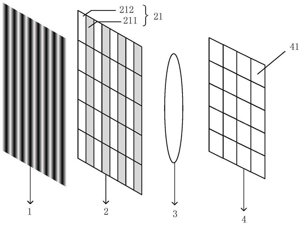
[0055] It is set that the absorption and phase information of objects within the range of the above four visible light pixel units have little or no change. The fringe is detected using a pixelated transition screen, such as Figure 8 The detection system shown includes X-ray interference fringes 1 , pixelated conversion screen 2 , visible ...
Embodiment 2
[0060] Example 2, such as Figure 9 As shown, in this embodiment, the pixel conversion screen with a special structure is used to recover the phase information of the object in the direction perpendicular to the period of the X-ray interference fringes.
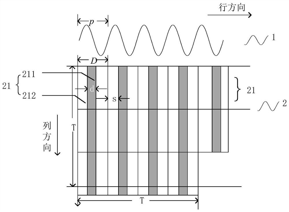
[0061] Take a 4-step phase shift as an example. Along the X-ray propagation direction, the X-ray interference fringes 1 of the imaging system, the spatial positions of the pixel conversion screen and the visible light detector are as follows: figure 2 As shown, the detailed relative position and size relationship are as follows Figure 9 shown. The direction of the X-ray interference fringe 1 is the row direction shown in the figure, and the phase information of the object is restored by using 4 pixel units (9-2) perpendicular to this direction, and the numbers of the 4 pixel units 21 are 1, 2, 3 respectively , 4. The width p of a single pixel unit of the pixel conversion screen is the same as the period p of the X-ray i...
Embodiment 3
[0063] Embodiment 3 is the third embodiment. In this embodiment, an absorption grating with a special structure is used to detect X-ray interference fringes.
[0064] like Figure 10 As shown, taking four visible light pixel units to restore the phase information of an object as an example, the specific structure of the absorption grating is explained in detail:
[0065] like Figure 10 As shown, from top to bottom are X-ray interference fringes 5 , absorption grating 6 , conversion screen 7 and visible light pixel unit 8 . The X-ray interference fringe period of the imaging system is p, and the period length of the absorption grating unit is the same as the X-ray interference fringe period p.
[0066] The periodic unit 61 of the absorption grating 6 includes a light-transmitting region 611 and an absorbing region 612. The single pixel of the positive visible light detector is a square, the side length is T, and the relationship with the length p of the periodic unit 61 of ...
PUM
 Abstract
Description
Claims
Application Information
 - R&D
- Intellectual Property
- Life Sciences
- Materials
- Tech Scout
- Unparalleled Data Quality
- Higher Quality Content
- 60% Fewer Hallucinations
Browse by: Latest US Patents, China's latest patents, Technical Efficacy Thesaurus, Application Domain, Technology Topic, Popular Technical Reports.
© 2025 PatSnap. All rights reserved.Legal|Privacy policy|Modern Slavery Act Transparency Statement|Sitemap|About US| Contact US: help@patsnap.com


