Short-cavity-length surface-emitting laser and manufacturing method thereof

A technology for emitting lasers and manufacturing methods, applied in lasers, laser parts, semiconductor lasers, etc., can solve problems such as process difficulties, and achieve the effects of reducing coating process, widening bandwidth, and improving utilization rate

Active Publication Date: 2018-01-23
WUHAN HUAGONG GENUINE OPTICS TECH
View PDF5 Cites 4 Cited by
  • Summary
  • Abstract
  • Description
  • Claims
  • Application Information

AI Technical Summary

Problems solved by technology

[0005] The object of the present invention is to provide a short-cavity long-surface-emitting laser and its manufacturing method. By integrating a section of passive waveguide regions on both sides of the gain region, the problem of difficult process caused by the small cavity length is solved.

Method used


Image

  • Short-cavity-length surface-emitting laser and manufacturing method thereof
  • Short-cavity-length surface-emitting laser and manufacturing method thereof
  • Short-cavity-length surface-emitting laser and manufacturing method thereof

Examples


Embodiment Construction

[0029] The following will clearly and completely describe the technical solutions in the embodiments of the present invention with reference to the accompanying drawings in the embodiments of the present invention. Obviously, the described embodiments are only some, not all, embodiments of the present invention. Based on the embodiments of the present invention, all other embodiments obtained by persons of ordinary skill in the art without making creative efforts belong to the protection scope of the present invention.

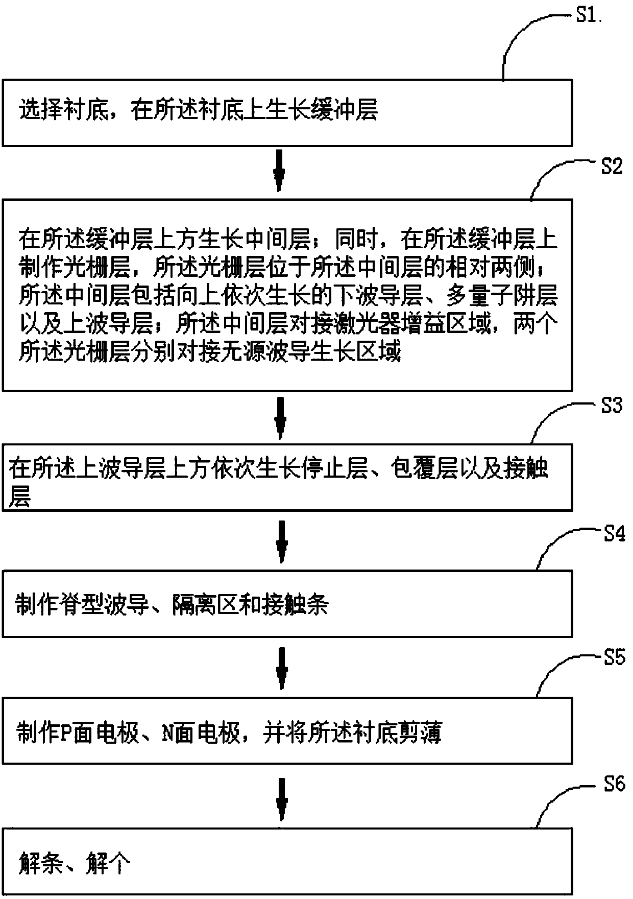
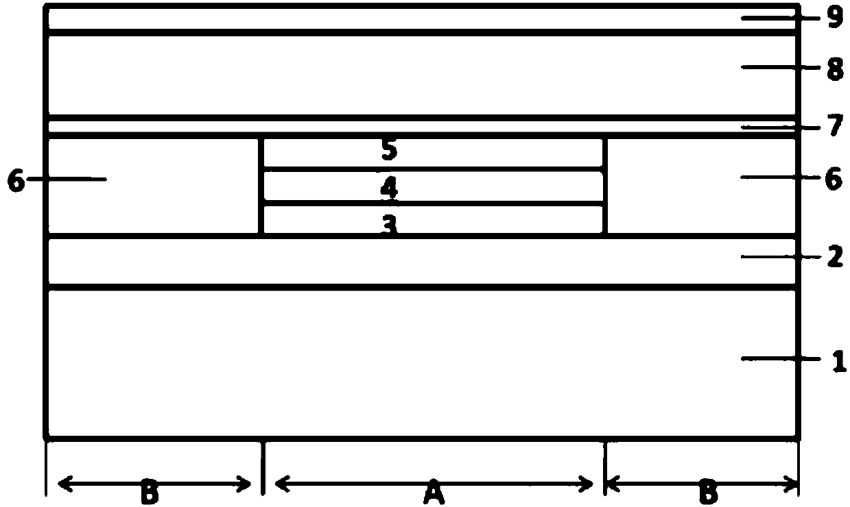
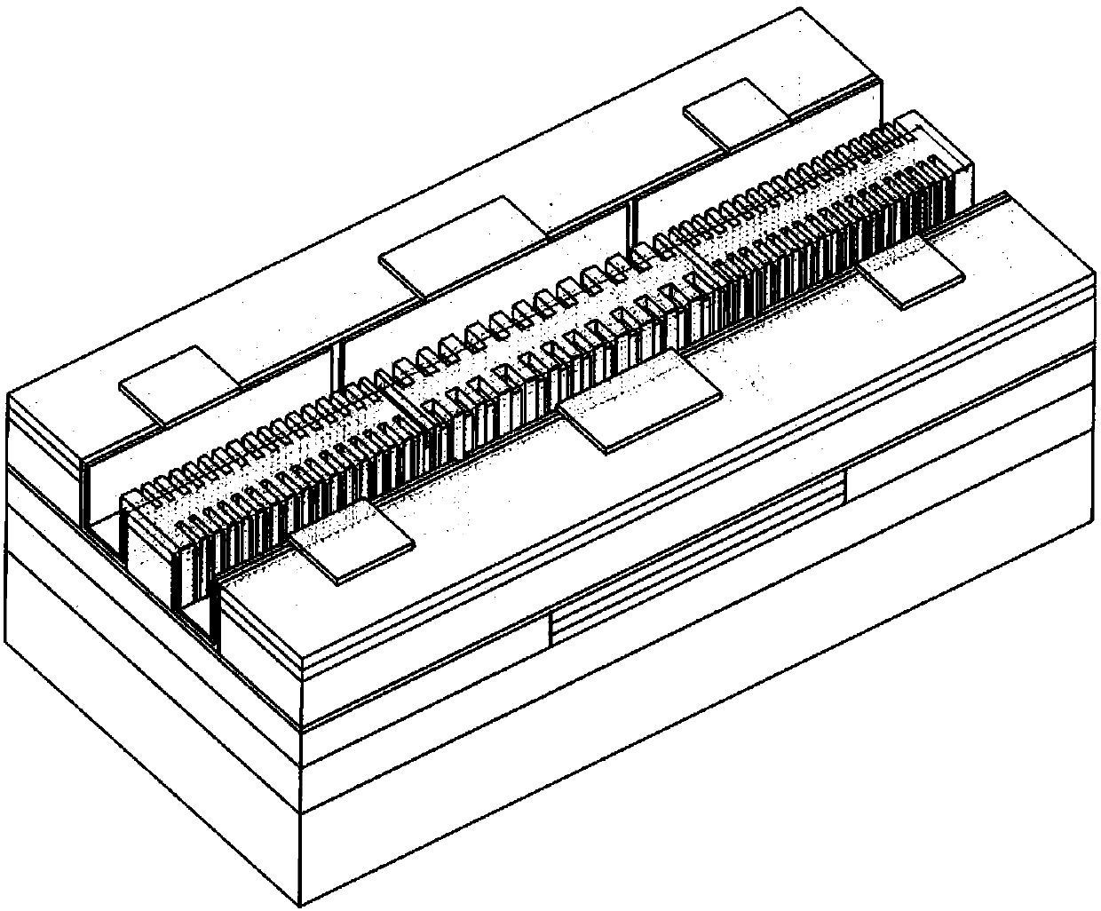
[0030] see figure 1 , figure 2 as well as image 3 , an embodiment of the present invention provides a method for manufacturing a short cavity long surface emitting laser, comprising the following steps: S1, select a substrate 1, and grow a buffer layer 2 on the substrate 1; S2, on the buffer layer 2 Growth intermediate layer; meanwhile, make grating layer 6 on described buffer layer 2, and described grating layer 6 is positioned at the opposite two sides o...


PUM


Abstract

The invention relates to the field of photoelectronic devices and provides a manufacturing method of a short-cavity-length surface-emitting laser. The method comprises the following steps of (S1) selecting a substrate and growing a buffer layer on the substrate; (S2) growing a middle layer at the upper part of the buffer layer, and simultaneously manufacturing grating layers on the buffer layer, wherein the grating layers are located at two opposite sides of the middle layer; and the middle layer comprises a lower waveguide layer, a multi-quantum well layer and an upper waveguide layer which are sequentially grown upwards; the middle layer is docked with a laser gain region; and the two grating layers are docked with passive waveguide growth regions separately; (S3) sequentially growing astop layer, a coating layer and a contact layer at the upper part of the upper waveguide layer; (S4) manufacturing a ridge waveguide, an isolation region and a contact bar; (S5) manufacturing a P surface electrode and an N surface electrode and thinning the substrate; and (S6) splitting the bar and individuals. A segment of passive waveguide region is integrated at each of two sides of the gain region, so that the problem of technological difficulties caused by a small cavity length is solved.

Description

technical field [0001] The invention relates to the field of optoelectronic devices, in particular to a short cavity long surface emitting laser and a manufacturing method thereof. Background technique [0002] The system upgrade of the optical network all benefits from the upgrade of the optical device. As the core component of the optical device, the performance of the laser restricts the performance of the entire system. Lasers that can achieve a single-channel baud rate of 25Gb / s or even better are urgently needed. demand. [0003] At present, there are two main schemes for high-speed modulated lasers. The first is distributed feedback laser monolithic integrated electro-absorption modulators (EMLs). EMLs are not affected by frequency chirp characteristics, and have relatively good extinction ratio and clear eye diagram. , very suitable for long-distance transmission systems. However, the manufacturing process is relatively complicated, and the power consumption is rel...

Claims


Application Information

Patent Timeline
Patent Type & Authority Applications(China)
IPC IPC(8): H01S5/18H01S5/183
Inventor 陈鑫李鸿建韩宇
Owner WUHAN HUAGONG GENUINE OPTICS TECH
Why Eureka
Try Eureka