Panoramic video monitoring method and system for motor vehicles

A monitoring system and panoramic video technology, applied in the field of panoramic video monitoring methods and systems for motor vehicles, can solve problems such as dead angles of spliced ​​views, length of vehicle body, and influence on the driver's effective observation of the vehicle body and surrounding areas, so as to avoid driving blind spots , increased flexibility, and easy-to-view results

Active Publication Date: 2022-05-17
鹰驾科技(深圳)有限公司
View PDF6 Cites 0 Cited by
  • Summary
  • Abstract
  • Description
  • Claims
  • Application Information

AI Technical Summary

Problems solved by technology

[0005] The object of the present invention is to provide a vehicle panoramic monitoring method and system for a vehicle, aiming to solve the following problems in the prior art panoramic video system for motor vehicles: No dead angle monitoring; 2. The dynamic connection car cannot be completely stitched together and there is a problem of dead angle in the stitched view; 3. Due to the long body and the change in the angle of the connected car body, the panoramic view of the traditional bird's-eye view and the view of a single camera Unable to meet the driver's observation habits, affecting the driver's effective observation of the car body and surrounding areas; 4. The problem of not being able to accurately calculate and draw the dynamic trajectory of the trailer part for the dynamically connected car

Method used


Image

  • Panoramic video monitoring method and system for motor vehicles
  • Panoramic video monitoring method and system for motor vehicles
  • Panoramic video monitoring method and system for motor vehicles

Examples


Embodiment 1

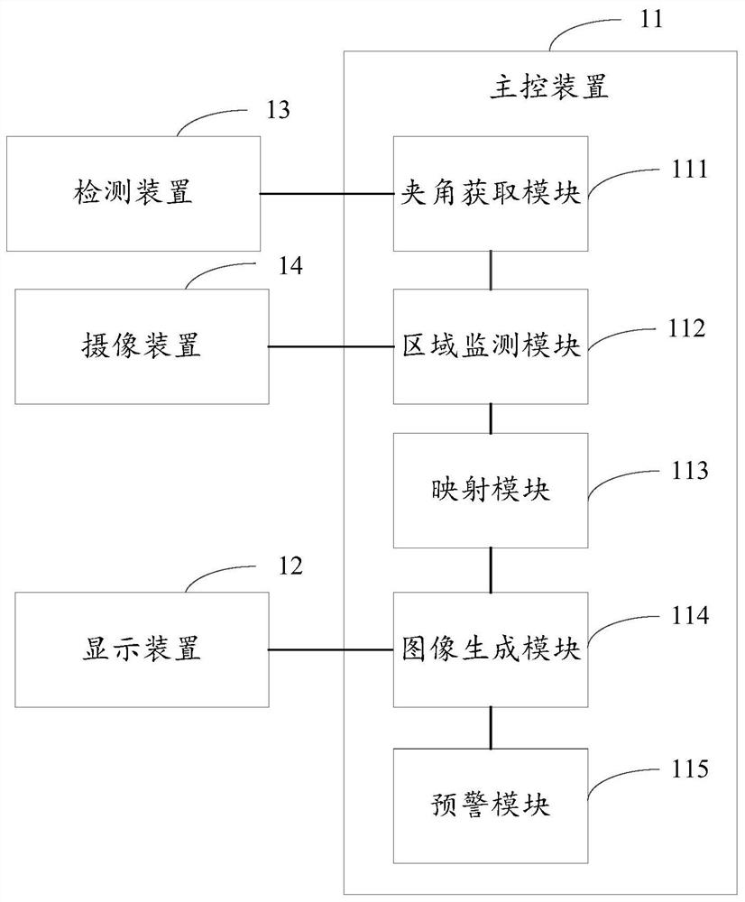
[0034] figure 1 A structural diagram of a panoramic video monitoring system for a motor vehicle provided by Embodiment 1 of the present invention is shown, as shown in figure 1 As shown, the system provided by the embodiment of the present invention includes a main control device 11 , a display device 12 connected to the main control device 11 , a recording device 13 , and a plurality of camera devices 14 . The main control device 11 may include an angle acquisition module 111 , an area monitoring module 112 , a mapping module 113 and an image generation module 114 .

[0035] The recording device 13 may be a sensor for acquiring an angle, such as an angle sensor for acquiring the turning angle between the main vehicle and the trailer, including but not limited to mechanical, infrared and other angle sensors. The camera device 14 can be used to acquire input video, and the input video can be in various forms such as analog and digital.

[0036] The included angle obtaining mo...

Embodiment 2

[0064] image 3 A schematic diagram of a panoramic video monitoring system for a motor vehicle provided in Embodiment 2 of the present invention is shown, as shown in image 3 As shown, it includes an angle sensor 31, a multi-channel camera 32, a CAN communication unit 33, a video recording and playback unit 34, a vehicle-mounted display unit 35 and a main control board 36, wherein the main control board 36 can be found in figure 1 For the main control device in the described embodiment, the angle sensor 31 can be referred to figure 1 For the recording device in the described embodiment, the multi-channel camera 32 can be referred to figure 1 For the camera device in the described embodiment, the on-board display unit 35 can be referred to figure 1 The display device in the described embodiment.

[0065] The angle sensor 31 is used to obtain the turning angle between the front of the vehicle and the body, including but not limited to mechanical, infrared and other angle sen...

Embodiment 3

[0067] Figure 4 The implementation flowchart of the panoramic video monitoring method for motor vehicles provided by the third embodiment of the present invention is shown, including steps S401 to S404, and the details are as follows:

[0068] Step S401, acquiring the angle between the central axis of the main vehicle of the motor vehicle and the central axis of the trailer of the motor vehicle.

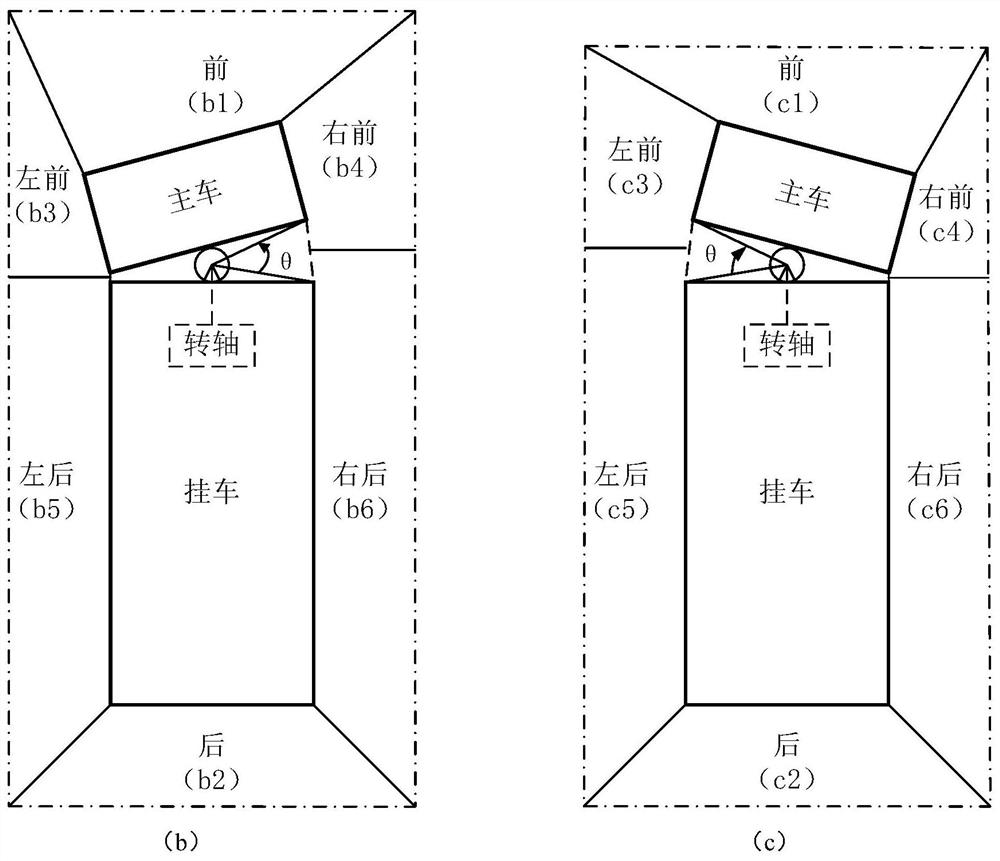
[0069] As an optional embodiment, the angle between the central axis of the main vehicle of the motor vehicle and the central axis of the trailer of the motor vehicle can be detected. For example, the angle between the central axis of the main vehicle of the motor vehicle and the central axis of the trailer of the motor vehicle can be detected by the angle sensor. like figure 2 As shown, when the main vehicle of the motor vehicle rotates, it can be obtained that the central axis of the main vehicle forms an included angle θ with the central axis of the trailer.

[0070] Step S402,...


PUM


Abstract

The present invention is applicable to the field of automotive electronics, and provides a panoramic video monitoring method and system for motor vehicles, which can obtain the angle between the central axis of the main vehicle of the motor vehicle and the central axis of the trailer of the motor vehicle; and confirm the monitoring according to the obtained angle The monitoring area includes multiple sub-areas, and the multiple sub-areas constitute the panoramic area of ​​the motor vehicle; the mapping from the coordinates of each sub-area in the monitoring area to the coordinates of the display screen is established; a panoramic image is generated and displayed on the display screen according to the mapping establishment result. Therefore, the monitored sub-area can be confirmed according to the angle between the main vehicle and the trailer of the motor vehicle, and the monitoring area changes dynamically with the state of the motor vehicle. The driving track line realizes the complete panorama stitching of the dynamically connected vehicles, monitors multiple or more than two dynamically connected vehicles without blind spots, and improves the accuracy of the panoramic monitoring of motor vehicles.

Description

technical field [0001] The invention belongs to the technical field of automotive electronics, and in particular relates to a panoramic video monitoring method and system for motor vehicles. Background technique [0002] The use of driving assistance systems in motor vehicles can effectively observe the blind spots of driving, and the panoramic video recording system usually installs more than one camera around the vehicle body, so that the viewing angle covers all or most of the area around the vehicle body. And by directly displaying the camera video in different areas on the screen; or by the method of image video splicing, transform and splicing several camera videos to form: 1. A panoramic image with a bird's-eye view, intuitively showing the positional relationship between the vehicle body and the surrounding environment; 2. Display single-channel or multi-channel camera video from a special perspective, for example, from the driver's perspective from the left and righ...

Claims


Application Information

Patent Timeline
Patent Type & Authority Patents(China)
IPC IPC(8): B60R1/27
Inventor 段侪杰张飞龙郑智宇
Owner 鹰驾科技(深圳)有限公司
Why Eureka
Try Eureka