Pod rotation hydraulic drive system

A drive system, hydraulic technology, applied in the direction of fluid pressure actuation devices, non-mechanical gear transmission devices, etc., can solve the problems of low efficiency and poor stability, and achieve the effect of avoiding energy loss, increasing stability and improving efficiency.

Inactive Publication Date: 2018-01-26
成都源云机械有限公司
View PDF0 Cites 7 Cited by
  • Summary
  • Abstract
  • Description
  • Claims
  • Application Information

AI Technical Summary

Problems solved by technology

The drive of the slewing system can be divided into electric slewing drive and hydraulic slewing drive according to the difference in power source; when hydraulic drive i

Method used


Image

  • Pod rotation hydraulic drive system

Examples


Embodiment Construction

[0009] The embodiments of the present invention will be further described below in conjunction with the accompanying drawings.

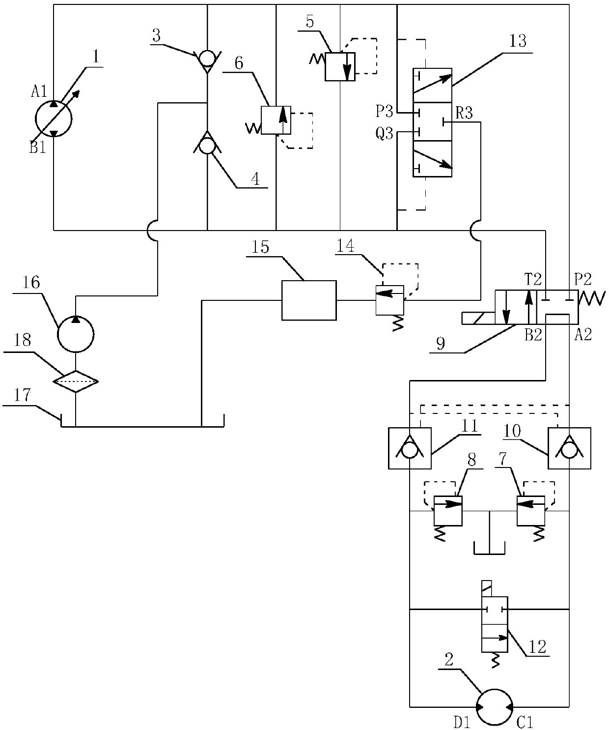
[0010] Such as figure 1 As shown, a pod rotation hydraulic drive system provided by the present invention is suitable for the use of pod rotation. The pod rotation hydraulic drive system includes a bidirectional variable pump 1, a hydraulic motor 2, a first one-way valve 3, a second one-way Directional valve 4, first relief valve 5, second relief valve 6, third relief valve 7, fourth relief valve 8, two-position four-way solenoid valve 9, first hydraulic control check valve 10, second relief valve Two hydraulically controlled one-way valves 11, two-position two-way solenoid valves 12, flushing valves 13, back pressure valves 14, coolers 15, charge pumps 16 and oil tanks 17.

[0011] The A1 port of the bidirectional variable pump 1 is connected to the P2 port of the two-position four-way solenoid valve 9, the B1 port of the two-way variable variable ...


PUM


Abstract

The invention relates to the technical field of pod rotation devices, in particular to a pod rotation hydraulic drive system. The pod rotation hydraulic drive system includes a bi-directional variablepump, a hydraulic motor, a first one-way valve, a second one-way valve, a first overflow valve, a second overflow valve, a third overflow valve, a fourth overflow valve, a two-position four-way solenoid valve, a first hydraulic control one-way valve, a second hydraulic control one-way valve, a two-position two-way solenoid valve, a washing valve, a counterbalance valve, a cooler, and an oil pump.A closed loop design is adopted, energy loss due to an opened loop is avoided, the efficiency is improved, and the stability is enhanced. The first hydraulic control one-way valve and the second hydraulic control one-way valve can achieve self-locking of the hydraulic motor so as to allow the hydraulic motor to be in a stable state as static; and the two-position two-way solenoid valve can achieve free slide rotation of the hydraulic motor, energy can be saved, and the working efficiency is improved.

Description

technical field [0001] The invention relates to the technical field of a car turning device, in particular to a car turning hydraulic drive system. Background technique [0002] When a ship equipped with a pod propulsion device is sailing, the power of the navigation is provided by the pod propulsion system, and the yaw or reverse course of the ship needs to be realized by the pod slewing system. The performance of the pod slewing system will directly affect the maneuverability and maneuverability of the ship. The drive of the slewing system can be divided into electric slewing drive and hydraulic slewing drive according to the difference of power source; when hydraulic drive is used, it is generally realized by turning the slewing gear in the slewing system, but the existing pod slewing hydraulic drive system has poor stability ,low efficiency. Contents of the invention [0003] The object of the present invention is to provide a pod turning hydraulic drive system with ...

Claims


Application Information

Patent Timeline
IPC IPC(8): B63H23/26F15B15/18
Inventor 陈泊其
Owner 成都源云机械有限公司
Why Eureka
Try Eureka