

Slurry kinetic energy conversion device suitable for directional drilling construction in large drop mountain
A kinetic energy conversion and large drop technology, which is applied in the drilling drive device, directional drilling, drilling equipment and other directions in the wellbore, can solve the problems of insufficient hole lubrication, large drop, difficult to discharge rock debris in time, etc. Drive performance, reduce energy consumption, avoid offset effects
- Summary
- Abstract
- Description
- Claims
- Application Information
AI Technical Summary
Problems solved by technology
Method used
Image

Examples
Embodiment 1
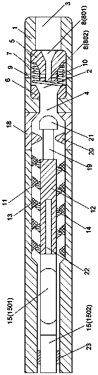
[0021] Such as figure 1 A mud kinetic energy conversion device suitable for directional drilling construction in a mountain with a large drop is shown, which includes a mud bypass valve and a mud drive device; the mud bypass valve includes a valve body 1 with a hollow structure, and the valve body 1 is provided with a valve chamber 2, and the valve body 1 includes a mud inlet 3 and a mud outlet 4 leading to the valve chamber 2, and the mud driving device and the mud outlet 4 are in communication with each other. Among the valve cavity 2, a valve core 5 is provided at the position corresponding to the mud inlet 3, a valve seat 6 is correspondingly provided at the mud outlet 4, and an elastic spring 7 is arranged between the valve core 5 and the valve seat 6; A guide hole 8 extending along its axial direction is provided in the center, and the end of the valve core 5 extends to the inside of the valve seat 6; a plurality of valve bodies are provided in the valve body 1 and lead ...
Embodiment 2
[0028] As an improvement of the present invention, such as figure 1 As shown, the through hole 8 of the valve core 5 includes a first end 801 relative to the mud inlet 3 and a second end 802 relative to the valve seat 6. The first end 801 of the through hole 8 The diameter of the first end portion 801 gradually decreases toward the second end portion 802 extending direction. Adopting the above-mentioned technical scheme, it can make the spool-phase conduction hole form a bucket-shaped structure for the mud inlet position, so as to ensure that the mud introduced by the mud inlet can quickly enter into the conduction space, and also make the mud flow to the spool. When pushing, it can pass through the side wall of the bucket-shaped structure to form a larger mud driving area, thereby improving the stability of the valve core during operation.
[0029] The remaining features and advantages of this embodiment are the same as those of Embodiment 1.
Embodiment 3
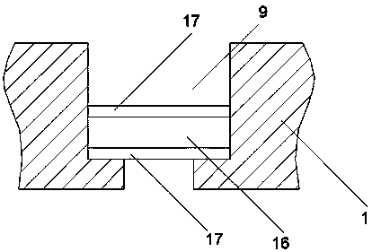
[0031] As an improvement of the present invention, such as figure 2 As shown, in the valve body, a sieve plate 16 is provided at the end of each bypass pipeline 9 , and partition plates 17 are respectively provided on both sides of the sieve plate 16 . With the above-mentioned technical solution, it is possible to prevent the rock fragments outside the bypass pipeline from entering the pipeline through the setting of the sieve plate, causing blockage or even damage to the equipment.
[0032] The remaining features and advantages of this embodiment are the same as those of Embodiment 2.
PUM
 Abstract
Description
Claims
Application Information