Novel high-temperature energy-saving fluidized bed furnace

A fluidized fluidized furnace, a new type of technology, applied in the field of high-temperature energy-saving new fluidized fluidized furnace, can solve the problems of difficult centralized dust collection treatment, poor coal particle boiling state, poor coal particle combustion effect, etc., to achieve improved efficiency, enhanced combustion effect, and good combustion effect Effect

Inactive Publication Date: 2018-01-26
盐城市吉盛达环保工程有限公司
View PDF0 Cites 0 Cited by
  • Summary
  • Abstract
  • Description
  • Claims
  • Application Information

AI Technical Summary

Problems solved by technology

[0003] However, the existing fluidized fluidized furnace has the following problems in use: the feed inlet is set on one side of the fluidized fluidized furnace, and the conveyor is used to transport it by itself, but because the temperature in the fluidized fluidized furnace is relatively high, the coal particles are only transported to the feed inlet, and are easy to accumulate in the fluidized fluidized furnace. The feed inlet, and then distribute the air through the air distribution plate set at the bottom, blowing the coal particles to form a boiling layer to burn the coal particles
The existing feeding device is very simple, the transported coal particles are easy to accumulate at the feed port, and the boiling state of the coal particles is poor, resulting in poor combustion effect of the coal particles, which is difficult to meet the further development of the industry and seriously affects the production efficiency; On the one hand, when the coal particles are burned, coal ash or even coal coke will be produced, which will be directly discharged from the air outlet to pollute the environment, and it is difficult to collect dust for centralized treatment; therefore, it is urgent to improve the structure of the fluidized fluidized furnace

Method used


Image

  • Novel high-temperature energy-saving fluidized bed furnace
  • Novel high-temperature energy-saving fluidized bed furnace

Examples


Embodiment Construction

[0016] The present invention will be further explained below in conjunction with the accompanying drawings and specific embodiments. It should be understood that the following specific embodiments are only used to illustrate the present invention and are not intended to limit the scope of the present invention.

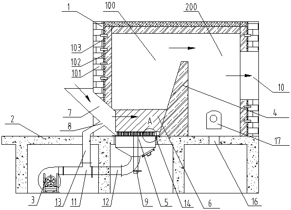
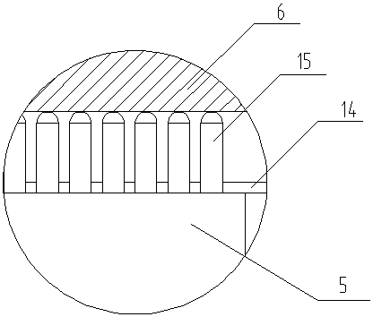
[0017] Such as figure 1 , figure 2 As shown, a fluidized fluidized furnace adopting a new type of fuel includes a furnace body 1, a bottom plate 2, and a fan 3; a fire wall 4 is provided in the middle of the bottom plate, and the fire wall separates the furnace body into a first furnace chamber 100 and a second furnace chamber 200; The bottom plate of the first furnace chamber is provided with a first air inlet 5, a fluidized bed 6 is arranged above the first air inlet, and a feed pipe 7 is provided on one side of the furnace body of the first furnace chamber, and the feed pipe extends obliquely through the furnace body. Into the furnace body, the upper and lower en...


PUM


Abstract

The invention discloses a novel high-temperature energy-saving fluidized bed furnace which comprises a furnace body, bottom plates and a fan. A fire barrier is arranged in the middle of the bottom plate and divides the furnace body into a first furnace chamber and a second furnace chamber; a first air inlet is formed in the bottom of the first furnace chamber, a boiling bed is arranged above the first air inlet, a feeding pipe is arranged on one side of the first furnace chamber, the feeding pipe penetrates through the furnace body obliquely to enter the furnace body, and the lower end of thefeeding pipe is located above the boiling bed; a second air inlet is formed in the middle section of the feeding pipe, an ash outlet is formed in the bottom plate of the second furnace chamber, and anair outlet is formed in the furnace body of the second furnace chamber; the fan is connected to a three-way joint, one end of the three-way joint is connected to a first air hose, the first air hoseis connected to the first air inlet while the other end of the three-way joint is connected to a second air hose, and the second air hose communicates to the second air inlet. The novel high-temperature energy-saving fluidized bed furnace disclosed by the invention increases the utilization ratio of fuels, is energy-saving and environment-friendly, good in boiling effect of coal particles, and more uniform in distribution of coal particle; the energy conversion efficiency is increased, and the combustion temperature is high.

Description

technical field [0001] The invention relates to the field of fluidized fluidized furnace devices, in particular to a new type of high-temperature energy-saving fluidized fluidized furnace. Background technique [0002] Fluidized bed combustion boiler is a kind of coal-fired boiler, which is one of the new combustion technologies developed in recent years. The working principle of the fluidized boiler is to blow the coal particles broken to a certain size with the wind, and burn them in a boiling state at a certain height in the furnace. , The thermal equipment that processes materials in this way is called fluidized fluidized furnace. The combustion of coal in a fluidized fluidized furnace is neither carried out on the grate nor suspended in space like a pulverized coal furnace, but is carried out on the fluidized furnace charge bed, so that the coal mine can be heated and reduced in a boiling state, which is beneficial Improve the quality of roasted ore. [0003] However...

Claims


Application Information

Patent Timeline
Patent Type & Authority Applications(China)
IPC IPC(8): F23C10/00F23C10/18F23C10/20F23C10/22F23L5/02
Inventor 李红兵周跃邦王明
Owner 盐城市吉盛达环保工程有限公司
Why Eureka
Try Eureka