A Grounded Coplanar Waveguide Duplexer Antenna

A technology of grounded coplanar waveguide and duplexer, which is applied in the direction of antenna, antenna coupling, antenna grounding device, etc., can solve the problems of increasing circuit size and high insertion loss, so as to reduce circuit size, increase power capacity, reduce small amount effect

Active Publication Date: 2019-10-11
上海卷积通讯技术有限公司
View PDF5 Cites 0 Cited by
  • Summary
  • Abstract
  • Description
  • Claims
  • Application Information

AI Technical Summary

Problems solved by technology

In order to further improve the isolation, many designs have introduced transmission zeros, but the generation of transmission zeros often requires multiple resonator coupling, which undoubtedly increases the circuit size, and the more coupled resonators, the more insertion loss will be brought

Method used


Image

  • A Grounded Coplanar Waveguide Duplexer Antenna
  • A Grounded Coplanar Waveguide Duplexer Antenna
  • A Grounded Coplanar Waveguide Duplexer Antenna

Examples


Embodiment 1

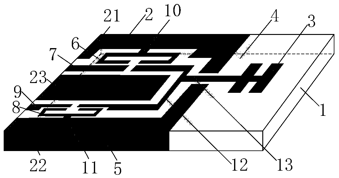
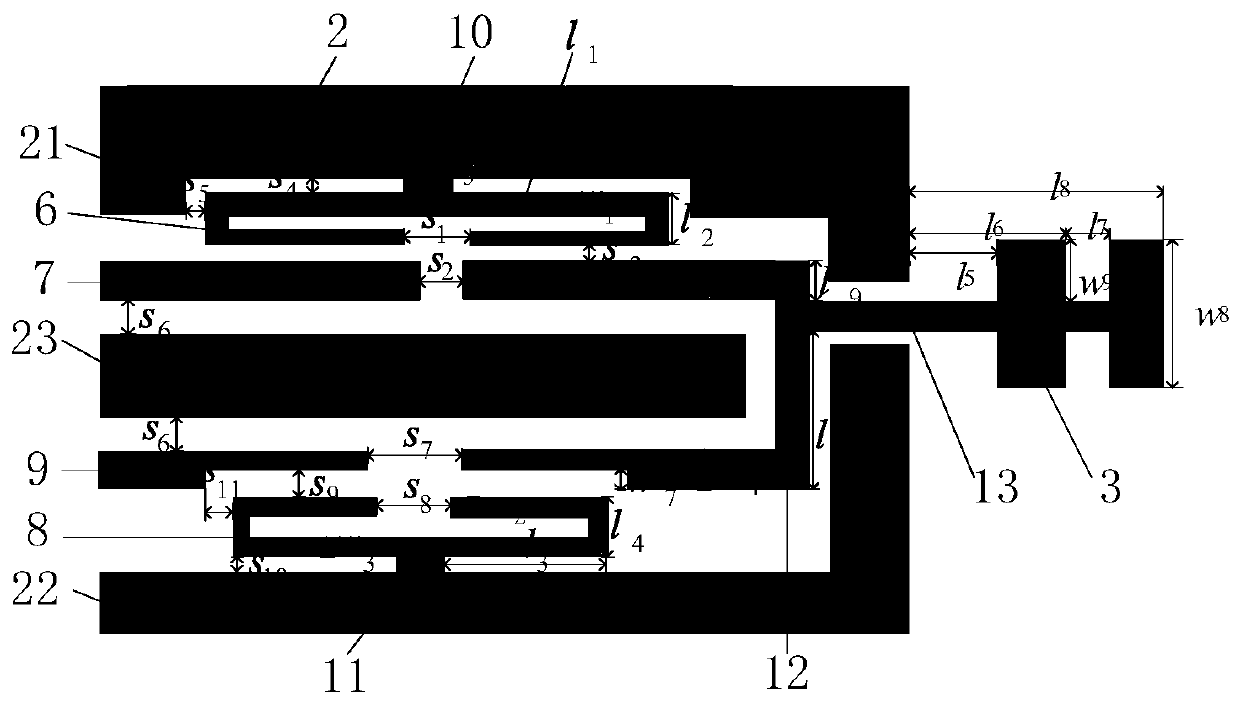
[0035] refer to figure 1 , a grounded coplanar waveguide duplexer antenna, comprising a dielectric substrate 1, the relative permittivity of the dielectric substrate 1 is 2.2, and the thickness of the dielectric substrate 1 is 0.8mm.

[0036] The upper surface of one side of the dielectric substrate 1 is printed with an upper grounding plate 2, and the lower surface is printed with a lower grounding plate 4, which are connected by side edge patches 5. The other upper surface of the dielectric substrate 1 is printed with The radiation patch 3; the upper grounding plate 2 is composed of a first L-shaped metal patch 21, a second L-shaped metal patch 22 and a rectangular metal patch 23 located between the two patches; The rectangular metal patch 23 is provided with a first open-loop resonator 6 with an opening and a first feeder 7 between it and the first L-shaped metal patch 21. The first open-loop resonator 6 with an opening The first L-shaped metal patch 21 is connected to the...

Embodiment 2

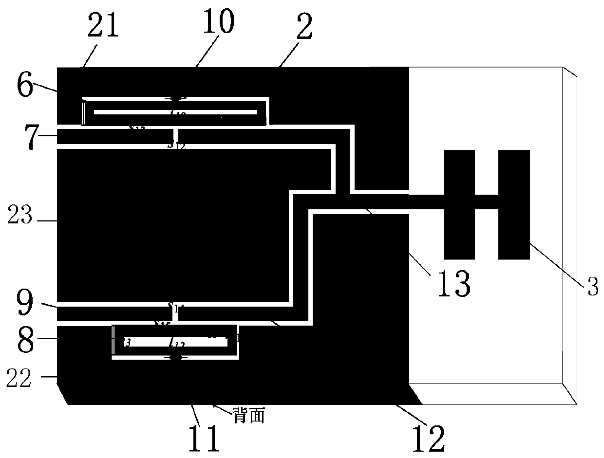
[0043] refer to image 3 and Figure 4 , this embodiment only changes the structure of the duplexer, and the radiation patch part can use a similar structure, which is finally integrated into a duplexer antenna.

[0044] A grounded coplanar waveguide duplexer antenna, comprising the same dielectric substrate 1 as in Embodiment 1, an upper ground plate 2 is printed on one side of the dielectric substrate 1, and a lower ground plate 4 is printed on the lower surface, And connected by the side edge patch 5, the other upper surface of the dielectric substrate 1 is printed with a radiation patch 3; the upper ground plate 2 is composed of a first L-shaped metal patch 21 and a second L-shaped metal patch A metal patch 22 and a rectangular metal patch 23 between the two patches; the rectangular metal patch 23 is provided with a first ring resonator 6 and a first L-shaped metal patch 21 between it and the first L-shaped metal patch 21. The first feeder 7, the first ring resonator 6 i...


PUM


Abstract

The invention provides a grounding coplanar waveguide diplexer antenna, aims to realize integrated design of a diplexer and an antenna and aims to improve electromagnetic shielding performance on thecondition that isolation of the diplexer is guaranteed. The grounding coplanar waveguide diplexer antenna comprises a medium substrate, and two open loop resonators, two feed wires and an upper grounding board which are arranged at one side of an upper surface of the medium substrate, a radiation patch arranged at the other side, and a lower grounding board printed on a lower surface of the mediumsubstrate, wherein the upper grounding board and the lower grounding board are connected through a side edge patch, the two open loop resonators are connected with the upper grounding board through grounding stub wires, electrical coupling is formed at an opening, a right transmission zero point of a channel is formed, the two grounding stub wires form magnetic coupling, a left transmission zeropoint of the channel is formed, and the upper grounding board, the lower grounding board, the two feed wires, the side edge patch and the two resonators form a grounding coplanar waveguide structure.The antenna is advantaged in that the volume is small, electromagnetic shielding performance is good, and the antenna can be applied to a micro radio frequency front system.

Description

technical field [0001] The invention belongs to the technical field of microwave antennas, and relates to an integrated ground coplanar waveguide duplexer antenna, which can be used in miniaturized radio frequency front-end systems. Background technique [0002] The research and development of microwave devices are closely related to the diversified development of communication systems and wireless applications. At present, wireless communication standards are constantly updated, wireless communication technology applications are changing with each passing day, and wireless resource spectrum is continuously expanding to higher frequency bands, which greatly promotes the development of RF front-end technology in the direction of high performance, miniaturization, low cost and integration. [0003] A coplanar waveguide (CPW) is a coplanar transmission line composed of three metal strips prepared on one surface of a dielectric substrate. The middle metal strip is a signal strip...

Claims


Application Information

Patent Timeline
Patent Type & Authority Patents(China)
IPC IPC(8): H01Q1/38H01Q1/48H01Q1/50H01Q1/52H01Q23/00
Inventor 肖建康苏小宝戚兴
Owner 上海卷积通讯技术有限公司
Why Eureka
Try Eureka