
Electric control mechanical driving clip dry cell self switching power supply device

A technology of mechanical drive and power supply device, applied in terminal battery switching devices and other directions, can solve the problems of time-consuming and laborious, unstable power supply, affecting the working efficiency of power-consuming devices, etc., and achieve the effect of improving detection efficiency and accuracy.

Inactive Publication Date: 2018-01-26
苏州麦喆思科电子有限公司
View PDF2 Cites 4 Cited by
  • Summary
  • Abstract
  • Description
  • Claims
  • Application Information

AI Technical Summary

Problems solved by technology

With the continuous development of technology, there are more and more types of power sources, ranging from large batteries to small lithium batteries. Because of the ubiquitous use of electricity in people's lives, power is ubiquitous, but the existing power supply is constantly improving. While its own power storage and power supply are stable, it often ignores the user-friendly experience of the power supply. As we all know, the existing power supply can be divided into rechargeable power supply and non-rechargeable power supply. In the process of using power supply for power supply, if Using a non-rechargeable power source for power supply has the advantage of stable power supply, but once the power is exhausted, it needs to be replaced with a non-rechargeable power source, which is time-consuming, laborious, and inefficient; Manual replacement, but it needs to be charged for the charging power source, and the power can be supplied again after the charging is completed. During this period, there will be a power outage period, which will affect the working efficiency of the electrical device; then, multiple charging is not conducive to the stability of the power in the power source. This makes the power supply in practical applications unstable, and also affects the working efficiency of electrical devices

Method used


Image

  • Electric control mechanical driving clip dry cell self switching power supply device
  • Electric control mechanical driving clip dry cell self switching power supply device

Examples


Embodiment Construction

[0017] The specific implementation manners of the present invention will be further described in detail below in conjunction with the accompanying drawings.

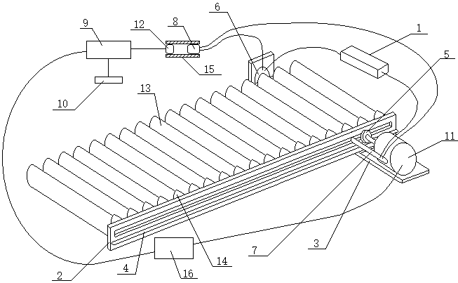
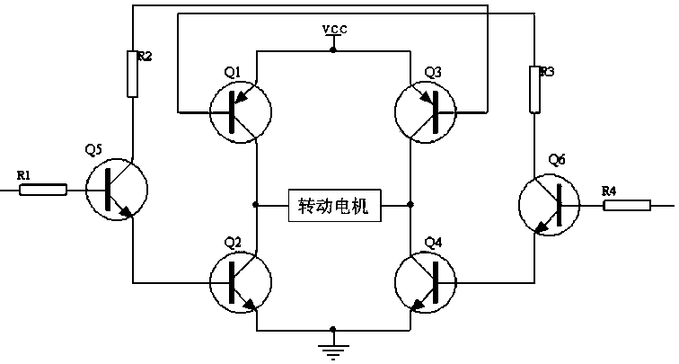
[0018] like figure 1 As shown, the present invention designs an electronically controlled mechanically driven clip-type dry battery self-switching power supply device, which uses a designated type of dry battery 13 to supply power to the electrical device 1; it includes a long strip 2 and a locking plate 3 with an L-shaped structure on the side , rack 4, gear 5, electrode sheet 6, conductive rod 7, strip conductive sheet, light source 8, rotating motor 11, at least two sleeves 14 and control module 9, and the independent power supply that is connected with control module 9 respectively Power supply 10, photosensitive sensor 12, motor drive circuit 16; Rotating motor 11 is connected with control module 9 through motor drive circuit 16; Wherein, independent power supply 10 supplies power for photosensitive sensor 12 throug...


PUM


Abstract

The invention relates to an electric control mechanical driving clip dry cell self switching power supply device and utilizes brand new structure design. A motor mechanical linkage structure is introduced, dry cells (13) are utilized to supply power for a light source (8), a light sensor (12) is utilized to detect whether the dry cells (13) are out of power, based on the mutual insection engagement principle, through a specifically-designed motor driving circuit (16), accurate control on a rotatable motor (11) is carried out, the rotatable motor (11) is utilized to drive a gear (5) to engage with a tooth bar (4), so a long-strip board (2) is made to move along with movement of the tooth bar (4), the dry cells (13) connected with a sleeve (14) are respectively switched to sequentially contact with an electrode (6), so the dry cells (13) are switched to work without gaps, and an electrical appliance (1) is supplied with power through the electrode (6) and a long-strip conductive sheet.

Description

technical field [0001] The invention relates to an electronically controlled mechanically driven clip-type dry battery self-switching power supply device, which belongs to the technical field of dry battery intelligent application. Background technique [0002] A power supply is a device that converts other forms of energy into electrical energy, that is, a device that provides power to electronic equipment, also known as a power supply, which provides the electrical energy required by all components in the equipment, the size of the power supply, whether the current and voltage are stable , will directly affect the working performance and service life of the equipment. With the continuous development of technology, there are more and more types of power sources, ranging from large batteries to small lithium batteries. Because of the ubiquitous use of electricity in people's lives, power is ubiquitous, but the existing power supply is constantly improving. While its own pow...

Claims


Application Information

Patent Timeline
Patent Type & Authority Applications(China)
IPC IPC(8): H02J7/36
Inventor 郑春秋
Owner 苏州麦喆思科电子有限公司
Learn More