Simple metal plate punching mechanism

A simple and simple technology for sheet metal, applied in the field of simple sheet metal punching mechanisms, can solve the problems of the thickness of the clamping device, the complex clamping mechanism, the large cutting impact, etc., and achieves firm and convenient clamping and convenient punching. , the effect of simple structure

Inactive Publication Date: 2018-01-30
FOSHAN RUIPUDA OPTOELECTRONICS TECH CO LTD
View PDF0 Cites 7 Cited by
  • Summary
  • Abstract
  • Description
  • Claims
  • Application Information

AI Technical Summary

Problems solved by technology

[0002] The sheet metal cutting mechanism of existing large-scale machining units is generally clamped by a clamping mechanism, and then cut off by an oil cylinder. It is generally suitable for large-volume sheet metal processing. The

Method used


Image

  • Simple metal plate punching mechanism

Examples


Embodiment

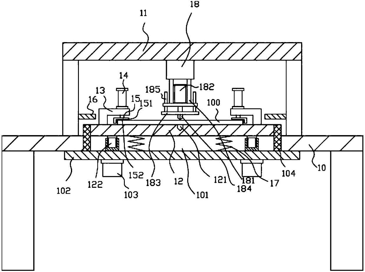
[0016] Example: see figure 1 As shown, a simple sheet metal blanking mechanism includes a frame 10, a main support frame 11 is fixed on the top surface of the top plate of the frame 10, and a fixing plate is placed on the middle top surface of the top plate of the frame 10 12. The middle part of the top plate of the frame 10 has a through groove 101, the middle part of the bottom surface of the top plate of the frame 10 is fixed with a lower connecting plate 102, and the two sides of the bottom surface of the lower connecting plate 102 are fixed with a lifting motor 103, and the output shaft of the lifting motor 103 passes through Pass the lower connecting plate 102 and insert it in the through groove 101. The top surface of the output shaft of the lifting motor 103 has a threaded hole, and the two sides of the bottom surface of the fixed plate 12 are fixed with adjusting studs 122. The adjusting studs 122 are screwed on in the screw hole;

[0017] The middle top surface of t...


PUM


Abstract

The invention discloses a simple metal plate punching mechanism which comprises a rack. A main supporting frame is fixed on the top surface of a top plate of the rack, a placement fixing plate is placed on the top surface of the middle of the top plate of the rack, a through groove is formed in the middle of the top plate of the rack, a lower connecting plate is fixed in the middle of the undersurface of the top plate of the rack, lifting motors are fixed on two sides of the undersurface of the lower connecting plate, an output shaft of each lifting motor penetrates the lower connecting plateand is inserted into the through groove in a sleeved manner, the top surface of the output shaft of each lifting motor is provided with a threaded connection hole, and adjusting studs are fixed on twosides of the undersurface of the placement fixing plate and connected in the threaded connection holes in a threaded manner; lateral supporting frames are fixed on the top surface of two sides of theplacement fixing plate, a compression oil cylinder is arranged on a top plate of each lateral supporting frame, a push rod of each compression oil cylinder penetrates the top plate of the corresponding lateral supporting frame and is fixed with a compression block, and the lower portions of opposite wall faces of the two compression blocks are provided with lower grooves. The simple metal plate punching mechanism is simple in structure, firm and convenient in clamping and suitable for thin small-size plates.

Description

Technical field: [0001] The invention relates to the technical field of hardware component manufacturing equipment, and more specifically relates to a simple metal plate punching mechanism. Background technique: [0002] The sheet metal cutting mechanism of existing large-scale machining units is generally clamped by a clamping mechanism, and then cut off by an oil cylinder. It is generally suitable for large-volume sheet metal processing. The clamping mechanism is complicated and the cutting impact is large. For thin The cutting of small-volume metal sheets is not ideal, consumes power, and the thickness of the clamping device is required, so it cannot clamp thin sheets. Invention content: [0003] The purpose of the present invention is to provide a simple sheet metal punching mechanism aimed at the deficiencies of the prior art, which has simple structure, firm and convenient clamping, convenient punching, and is suitable for thin and small-volume sheet metal. [0004]...

Claims


Application Information

Patent Timeline
IPC IPC(8): B21D28/02B21D28/14B21D28/04
Inventor 叶青
Owner FOSHAN RUIPUDA OPTOELECTRONICS TECH CO LTD
Why Eureka
Try Eureka