Concrete stirring machine

A technology for concrete mixers and mixing drums, applied in mixing plants, cement mixing devices, clay preparation devices, etc., can solve the problems of inaccurate mixing time control, uneven mixing of raw materials, and a large number of manpower feeding, so as to improve the quality of finished products and save The effect of manpower, convenient feeding and water delivery

Inactive Publication Date: 2018-01-30
赵伟胜
View PDF0 Cites 2 Cited by
  • Summary
  • Abstract
  • Description
  • Claims
  • Application Information

AI Technical Summary

Problems solved by technology

At present, mechanized concrete mixing is widely used on construction sites, which can save a lot of manpower and material resources. However, the existing concrete mixers

Method used


Image

  • Concrete stirring machine
  • Concrete stirring machine
  • Concrete stirring machine

Examples


Embodiment Construction

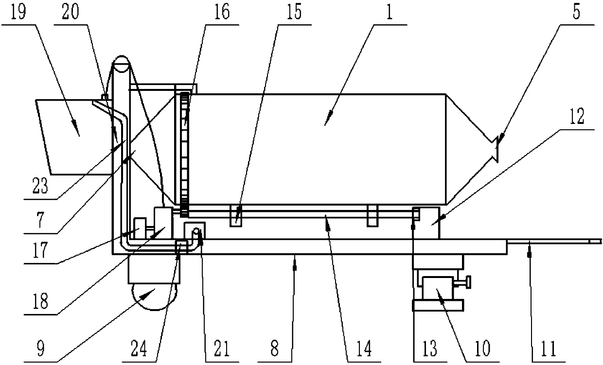
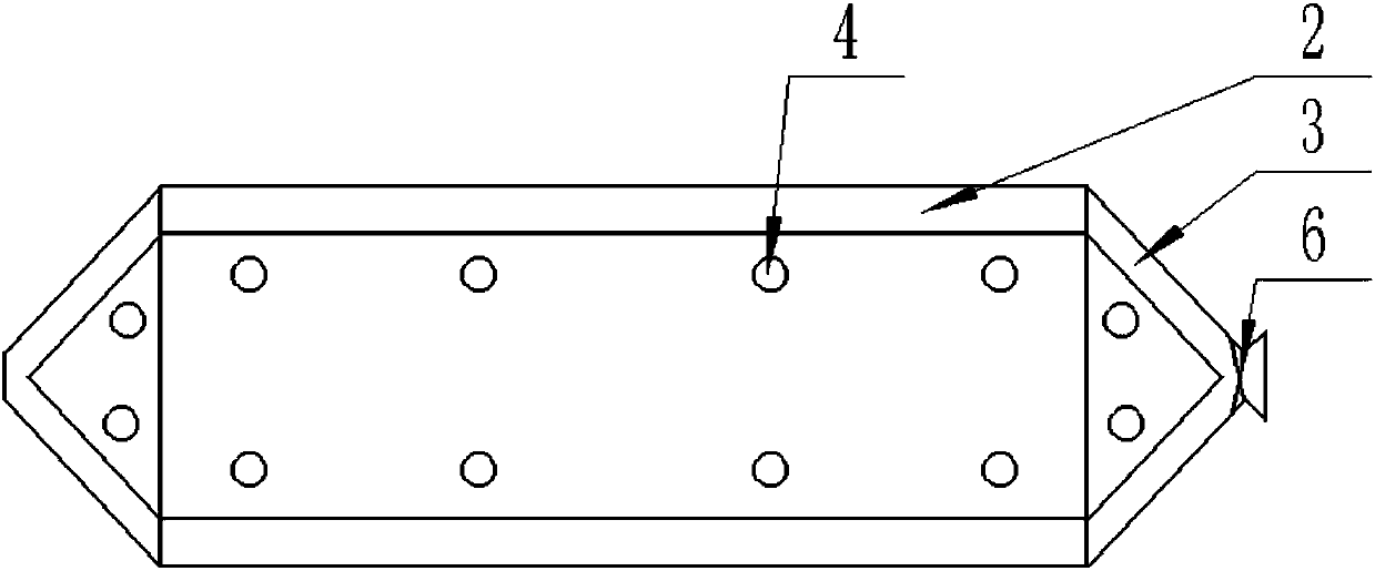
[0022] The present invention is specifically described below in conjunction with accompanying drawing, as Figure 1-6 As shown, a concrete mixer includes a mixing drum 1, the shape of the mixing drum 1 is biconical, and the mixing drum 1 is provided with a side liner 2 and an arc-shaped liner 3, and the side liner 2 and the The arc-shaped liner 3 is firmly connected with the inner wall of the mixing drum 1 by several screws 4. One end of the mixing drum 1 is provided with a discharge port 5, and a pair of semicircular blades 6 arranged in a high and low cross shape are provided at the discharge port 5. The opposite end of the mixing drum 1 to the discharge port 5 is provided with a feed inlet 7, a chassis 8 is provided below the mixing drum 1, and a pair of walking wheels 9 and a pair of supporting legs 10 are provided below the chassis 8, so that Two drawbars 11 are arranged on the chassis 8 and on both sides below the outlet 5, and two pairs of support blocks 12 are arranged...


PUM


Abstract

The invention discloses a concrete stirring machine. The concrete stirring machine comprises a stirring barrel, wherein the appearance of the stirring barrel is of a bi-conical shape, a side lining plate and an arc lining plate are arranged in the stirring barrel, one end of the stirring barrel is a material outlet, the other end of the stirring barrel is a material inlet, the material outlet is provided with a pair of semicircular blades which are distributed on different heights in a crossed shape, a chassis is arranged below the stirring barrel, the outer side of the material inlet is provided with a feeding mechanism, the feeding mechanism consists of a feeding hopper arranged obliquely above the material inlet, a feeding frame fixed on the chassis and supporting the feeding hopper, arotating motor arranged on the chassis, a rotating wheel connected with a motor rotating shaft and a lifting apparatus, the chassis is provide with a water supply system, the water supply system is formed jointly by a water pump installed on the chassis, a pipeline connected with the water pump and having a water outlet positioned on the feeding hopper, and an adjusting valve arranged on the pipeline, the chassis is provided with a controller, a PLC controller and a time relay are arranged in the controller, and the controller is provided with a control button. The concrete stirring machine has the beneficial effects of simple structure and high practicability.

Description

technical field [0001] The invention relates to the field of building construction, in particular to a concrete mixer. Background technique [0002] Concrete mixer is a mechanical equipment used to mix cement, sand and water and stir into concrete mixture. It is mainly composed of mixing drum, feeding mechanism, water supply system, driving mechanism, frame and supporting device. At present, mechanized concrete mixing is widely used on construction sites, which can save a lot of manpower and material resources. However, the existing concrete mixers still need a lot of manpower to feed materials and water when feeding, and there are uneven mixing of raw materials and inaccurate control of mixing time. And other issues. Contents of the invention [0003] The purpose of the present invention is in order to solve the above-mentioned problem, has designed a kind of concrete mixer. [0004] To achieve the above object, the technical solution of the present invention is, a conc...

Claims


Application Information

Patent Timeline
IPC IPC(8): B28C5/20B28C7/02B28C7/06B28C7/12B28C9/04
Inventor 赵伟胜
Owner 赵伟胜
Why Eureka
Try Eureka