Slurry sintering device for producing soft magnetic ferrite particles

A soft ferrite and sintering device technology, applied in the manufacturing of magnetic materials, magnetic objects, inductors/transformers/magnets, etc., can solve the problems of low efficiency, bloated equipment, and can not meet the needs of use, and achieve accurate cutting and mixing. material, the sintering effect is better, and the effect that meets the needs of use

Active Publication Date: 2020-05-08
安徽朗基新材料科技有限公司
View PDF4 Cites 0 Cited by
  • Summary
  • Abstract
  • Description
  • Claims
  • Application Information

AI Technical Summary

Problems solved by technology

[0003] In the process of processing the existing soft ferrite particles, various raw materials need to be mixed first and then poured into the sintering tank during sintering, which requires the participation of stirring equipment, which is time-consuming, laborious, bloated and inefficient. Can not meet the needs of people in production and life

Method used


Image

  • Slurry sintering device for producing soft magnetic ferrite particles
  • Slurry sintering device for producing soft magnetic ferrite particles
  • Slurry sintering device for producing soft magnetic ferrite particles

Examples


Embodiment 1

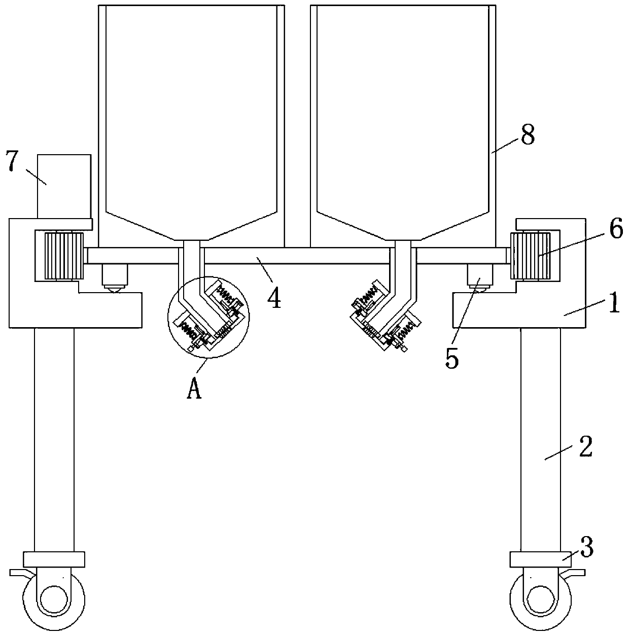
[0021] refer to Figure 1-3 A slurry sintering device for producing soft ferrite particles, comprising a mounting plate 1, the plate body of the mounting plate 1 is provided with a circular vertical through hole, and the top edge of the circular vertical through hole is provided with a ring groove, the bottom side of the mounting plate 1 is fixedly connected with several support columns 2, the inner side of the mounting plate 1 is provided with a support plate 4, and the bottom edge of the support plate 4 is provided with several equidistant ball universal balls 5, The bottom side of the universal ball 5 is in rolling contact with the inner wall of the bottom side of the ring groove. The vertical inner wall of the ring groove is provided with several side grooves, and the side grooves are rotated and connected with the limited rolling gear cylinder 6. The vertical one of the support plate 4 There is an external tooth groove on the side, and one side of the limiting rolling gea...

Embodiment 2

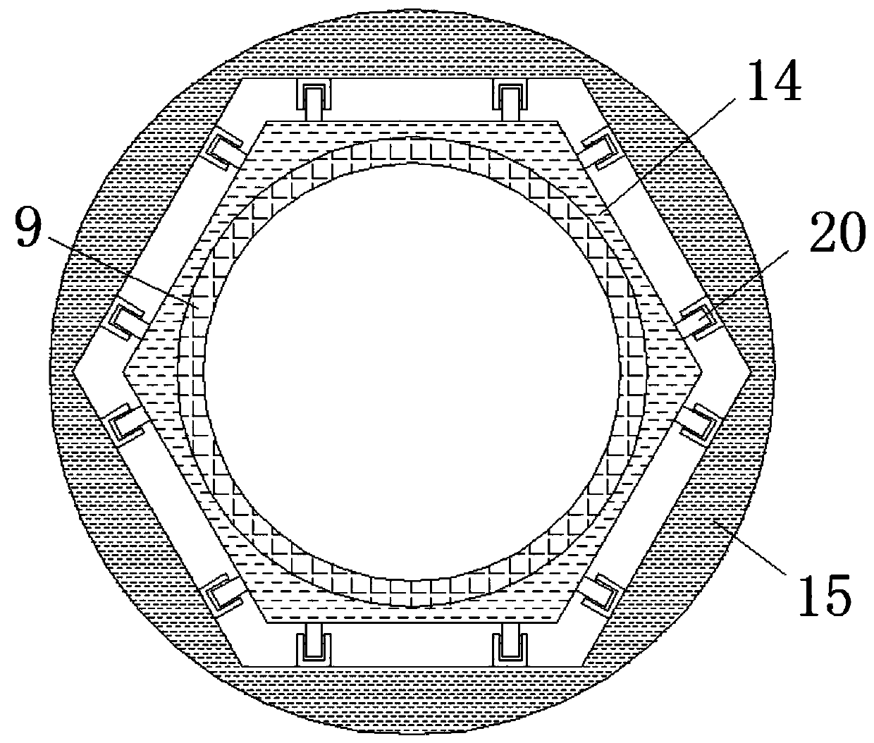
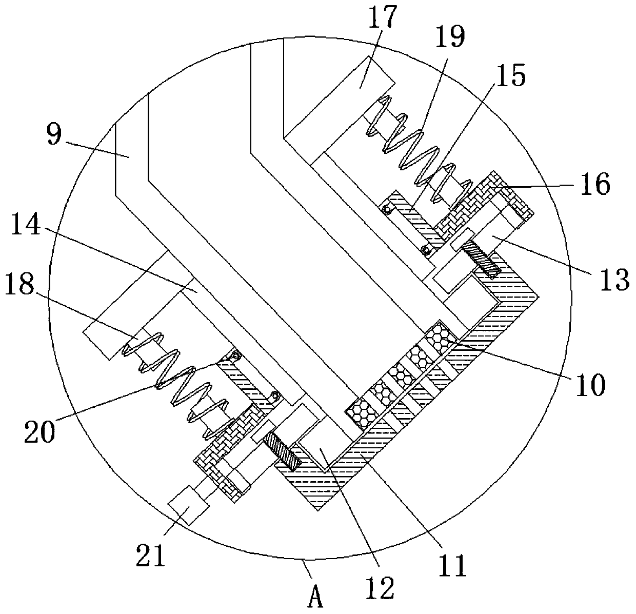
[0024] refer to Figure 1-3 , in this embodiment, it is basically the same as Embodiment 1, and more optimally, rollers 20 are provided on the inner walls of both ends of the sliding cylinder 15, and one side of the rollers 20 is connected in rolling contact with the inner wall of the polygonal track cylinder 14, and the ring gear cover One side of 16 is fixedly connected with handle 21, and the setting of handle 21 and roller 20 makes the movement of ring gear cover 16 smoother and labor-saving, and facilitates people's adjustment to the material passing hole. The inner side of sliding cylinder 15 is a polygonal structure, sliding The outer circular structure of the cylinder 15, the cooperation of the polygonal structure of the polygonal track cylinder 14 and the ring gear cover 16, and the elastic force of the return spring 19 make the engagement between the gear ring 13 and the ring gear cover 16 more stable, and play a role of insurance. As a result, the bottom ends of eac...


PUM


Abstract

The invention discloses a slurry sintering device for producing soft magnetic ferrite particles. The slurry sintering device comprises a mounting plate, and a circular vertical through hole is formedin a plate body of the mounting plate; an annular groove is formed in the edge opening of the top of the circular vertical through hole; a plurality of supporting columns are fixedly connected to thebottom side of the mounting plate; a supporting plate is arranged on the inner side of the mounting plate; a plurality of universal balls which are arranged at equal intervals are arranged at the edgeof the bottom side of the supporting plate; and the bottom sides of the universal balls are in rolling contact connection with the inner wall of the bottom side of the annular groove, a plurality ofside grooves are formed in the vertical inner wall of the annular groove, limiting rolling tooth cylinders are rotatably connected into the side grooves, outer tooth grooves are formed in the verticalsides of the supporting plates, and one sides of the limiting rolling tooth cylinders extend into the annular groove and are in engaged connection with the limiting rolling tooth cylinders. Accordingto the slurry sintering device, various materials can be evenly mixed, discharging and mixing are accurate, then the sintering effect of the slurry sintering device is better, and the use requirements of people in production and life are met.

Description

technical field [0001] The invention relates to the technical field of production equipment for soft ferrite particles, in particular to a slurry sintering device for producing soft ferrite particles. Background technique [0002] Soft ferrite is a ferrimagnetic oxide mainly composed of Fe2O3, which is produced by powder metallurgy. There are several types such as Mn-Zn, Cu-Zn, Ni-Zn, etc. Among them, the output and consumption of Mn-Zn ferrite are the largest, and the resistivity of Mn-Zn ferrite is low, which is 1-10 ohms / meter, generally in Use at frequencies below 100kHZ. The resistivity of Cu-Zn and Ni-Zn ferrite is 102~104 ohm / m, and the loss in the radio frequency band of 100kHz~10MHz is small, so they are mostly used in radio antenna coils and radio intermediate frequency transformers. [0003] In the process of processing the existing soft ferrite particles, various raw materials need to be mixed first and then poured into the sintering tank during sintering, whic...

Claims


Application Information

Patent Timeline
Patent Type & Authority Applications(China)
IPC IPC(8): H01F1/34H01F1/36H01F41/02C01G49/00C01G53/00
CPCC01G49/0018C01G53/006H01F1/344H01F1/36H01F41/02
Inventor 王涛徐林东
Owner 安徽朗基新材料科技有限公司
Why Eureka
Try Eureka