A high-efficiency recycling production line for cutting waste

A technology for cutting waste and production lines, applied in ceramic molding machines, chemical instruments and methods, clay preparation devices, etc., can solve problems such as affecting product quality, and achieve the effect of improving the work of pouring concrete, saving resources, and not easy to change the structure.

Active Publication Date: 2022-04-12
济源亚升新型建材有限公司
View PDF7 Cites 0 Cited by
  • Summary
  • Abstract
  • Description
  • Claims
  • Application Information

AI Technical Summary

Problems solved by technology

[0004] However, in the actual use process, the inventor found that when the waste material is recycled to the main material, it is necessary to control the quantitative ratio between the waste material and the main material. If the ratio is not accurate, it will affect the product quality.

Method used


Image

  • A high-efficiency recycling production line for cutting waste
  • A high-efficiency recycling production line for cutting waste
  • A high-efficiency recycling production line for cutting waste

Examples


Embodiment 1

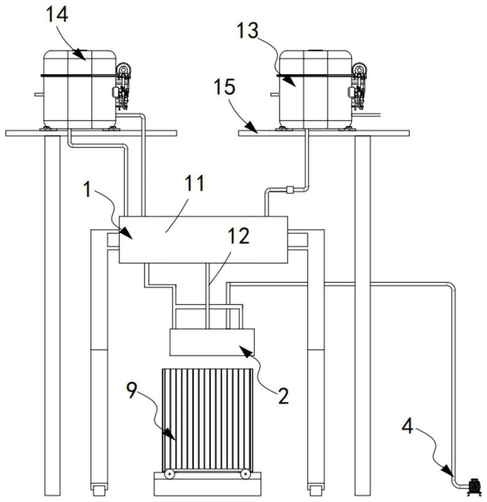
[0063] Such as figure 1 As shown, a production line for efficient recycling of cutting waste, including:

[0064] A material preparation mechanism 1, which includes a material storage bin 11, a feeding assembly 12 arranged at the output end of the storage bin 11, and a batching assembly 13 arranged above the storage bin 11;

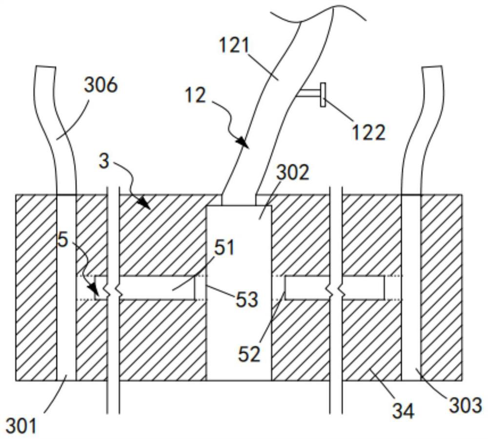
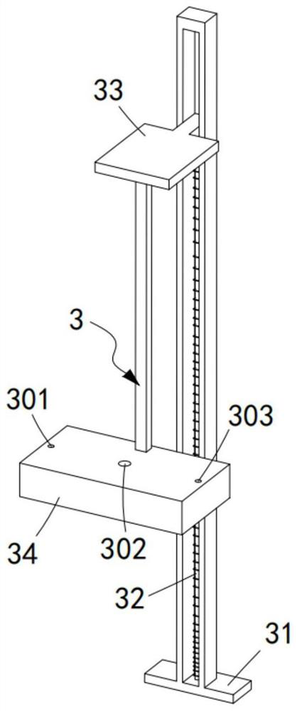
[0065] The unloading mechanism 2, the unloading mechanism 2 includes the lifting assembly 3 that is communicated with the feeding assembly 12 and is slidably arranged in the vertical direction, and is used to drive the lifting assembly 3 to move up and down in the vertical direction and intermittently start The driving assembly 4, the feeding assembly 5 arranged in the lifting assembly 3 and the exhaust assembly 6 arranged in the lifting assembly 3, the feeding assembly 5 and the exhaust assembly 6 pass through the switching assembly 7 Perform alternate work, the switching assembly 7 and the exhaust assembly 6 are set in linkage and synchronous transmiss...

Embodiment 2

[0106] Such as Figure 5 to Figure 7 As shown, the components that are the same as or corresponding to those in the first embodiment are marked with the corresponding reference numerals in the first embodiment. For the sake of simplicity, only the differences from the first embodiment will be described below. The difference between this embodiment two and embodiment one is:

[0107] further, such as Figure 5 to Figure 7 As shown, the exhaust assembly 6 includes a driving member 61 installed in the sealing plate 34 and installed in the installation groove 304 along the width direction of the sealing plate 34, and the exhaust gas that is driven by the driving member 61 62, a sealing member 63 arranged on the exhaust member 62, and a ventilation member 64 for discharging the gas discharged when the exhaust member 62 moves in the same direction.

[0108] In this embodiment, by setting the driver 61 to drive the exhaust piece 62, on the one hand, it can support and guide the exh...


PUM


Abstract

The invention relates to a high-efficiency recycling production line for cutting waste, including a material preparation mechanism, which includes a storage bin, a feeding assembly, and a batching assembly; a material unloading mechanism, which includes a lifting assembly, a driving assembly, a feeding The component and the exhaust component work alternately through the switching component, and the switching component and the exhaust component are set in linkage and synchronous transmission through the transmission component; and the material receiving mold (9); the gas discharged from the lifting component is automatically input into the storage bin Reuse is used as gas stirring power; the batching component includes a main material input component and a waste material input component, and the main material input component is driven by the driving component (4) to perform intermittent material spreading work; the invention solves the problem of recycling waste materials to main materials It is necessary to control the quantitative ratio between waste materials and main materials. If the ratio is not accurate, it will affect the technical problems of product quality.

Description

technical field [0001] The invention relates to the technical field of aerated concrete slabs / blocks, in particular to a high-efficiency recycling production line for cutting waste. Background technique [0002] The full name of the aerated concrete slab is the autoclaved aerated concrete slab. It uses silicon and calcium materials as the main raw materials, aluminum powder as the gas-generating material, and is equipped with anti-corrosion treated steel mesh. After adding water, stirring, pouring, Precured cut, autoclaved porous plate made. [0003] The patent document with the patent number CN2018113945498 discloses a method for preparing an aerated concrete slab, which includes the following steps: 1 selection of raw materials: weighing certain parts by mass of fly ash, lime, cement, gypsum, aluminum powder and water for use; Raw material processing: Grind the fly ash and gypsum selected in step 1, and pass the fly ash and gypsum after grinding through a 24-32 mesh sieve...

Claims


Application Information

Patent Timeline
Patent Type & Authority Patents(China)
IPC IPC(8): B28B13/02B28B17/00B28C5/08
CPCB28B13/022B28B13/0235B28B17/00B28C5/0831
Inventor 杨永泉邢广文纪德志
Owner 济源亚升新型建材有限公司
Why Eureka
Try Eureka