
Semiautomatic labeling machine for complicated-shape bottles

A special-shaped bottle and labeling machine technology, applied in the directions of labeling machine, labeling, labeling, etc., can solve the problems of inconvenient use, increased power consumption, time-consuming and laborious, etc., and achieve the effect of improving stability and avoiding noise.

Pending Publication Date: 2018-01-30
深圳市敦鼎智能自动化科技有限公司
View PDF0 Cites 4 Cited by
  • Summary
  • Abstract
  • Description
  • Claims
  • Application Information

AI Technical Summary

Problems solved by technology

[0002] In actual production, it is often necessary to stick label paper on the outside of the special-shaped bottle. In order to improve the efficiency of label paper sticking, the existing technology uses a labeling machine instead of manual labeling. When using a labeling machine to label special-shaped bottles, It is necessary to limit the position of the special-shaped bottle first. The labeling machine in the prior art mainly realizes the pressure and limit of the special-shaped bottle through the expansion and contraction of the piston rod of the cylinder. When the height of the special-shaped bottle changes, it is necessary to replace different stroke distances. The cylinder is time-consuming and laborious, and it is extremely inconvenient to use
[0003] When the air pressure of the cylinder changes, the effect of labeling will also change, and in severe cases, it will cause wrinkled labels; in addition, it is necessary to configure an additional air compressor for the cylinder, and the air compressor will also produce greater noise pollution , at the same time, the use of air compressors will also increase the consumption of electric energy, resulting in a significant increase in the cost of labeling

Method used


Image

  • Semiautomatic labeling machine for complicated-shape bottles
  • Semiautomatic labeling machine for complicated-shape bottles
  • Semiautomatic labeling machine for complicated-shape bottles

Examples


Embodiment Construction

[0033] In order to facilitate the understanding of those skilled in the art, the present invention will be further described below in conjunction with the embodiments and accompanying drawings, and the contents mentioned in the implementation modes are not intended to limit the present invention.

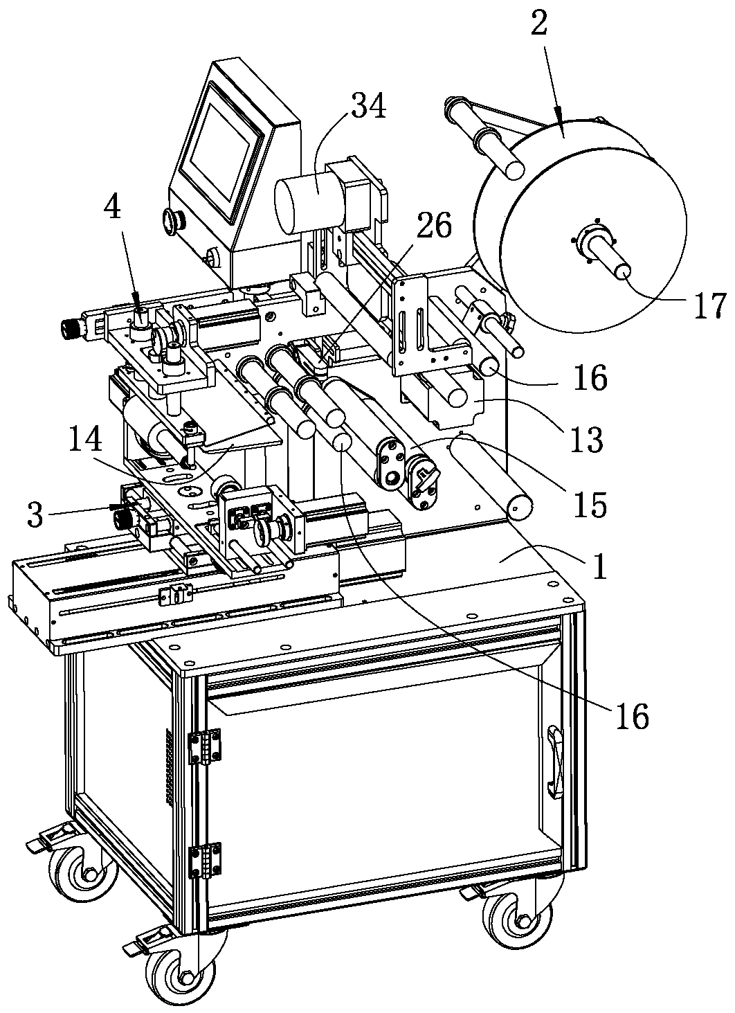
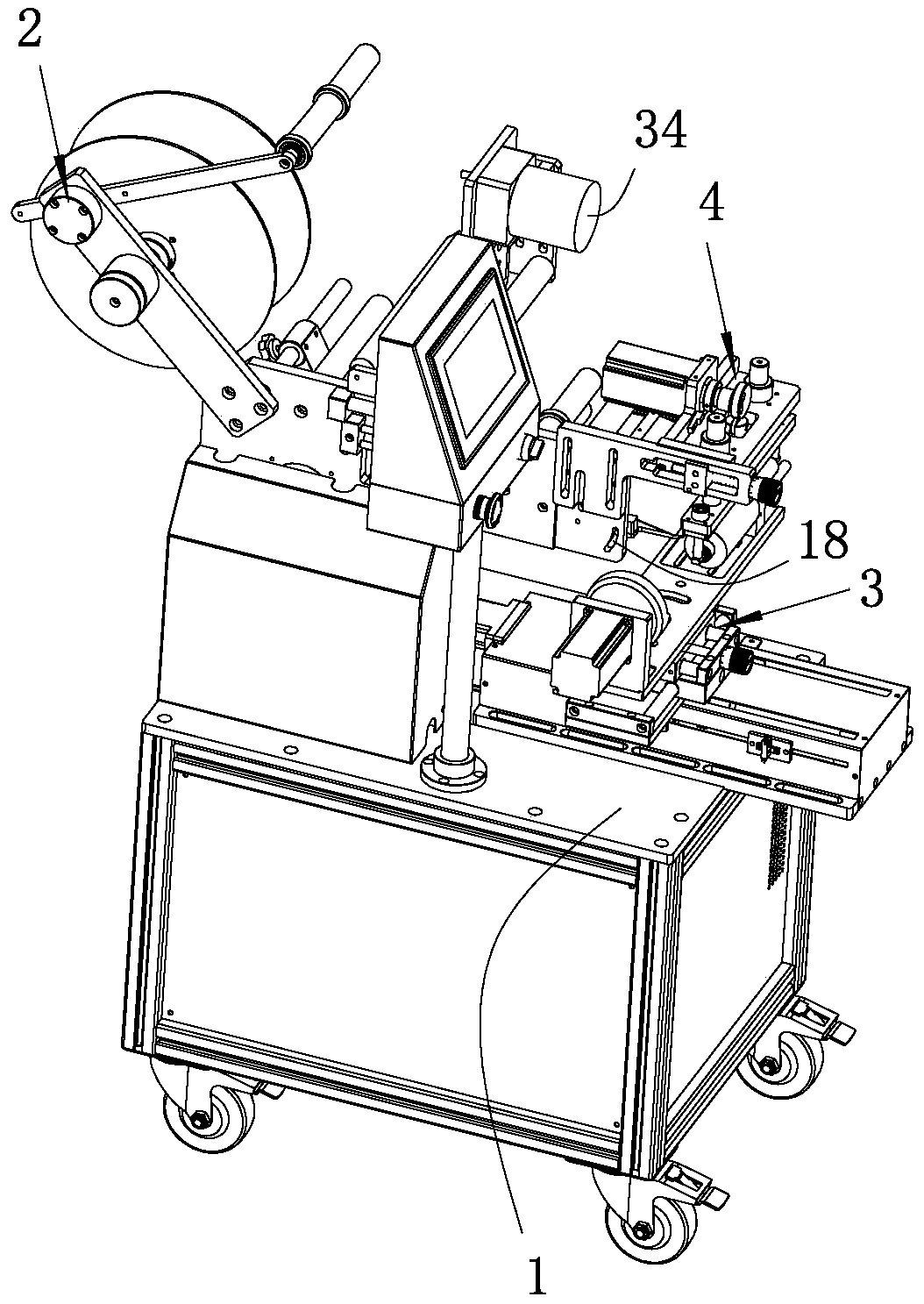
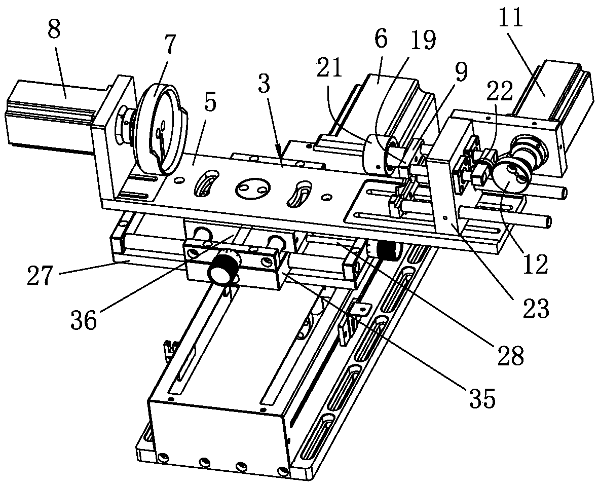
[0034] see Figure 1 to Figure 5 As shown, a semi-automatic special-shaped bottle labeling machine of the present invention includes a machine platform 1, a conveying mechanism 2 installed on the machine platform 1, a transfer mechanism 3 and a pressing mechanism 4, and the machine platform 1 is made of metal materials , the machine 1 includes a frame and a fixed plate installed on the frame, each mechanism is installed on the fixed plate of the machine 1, the conveying mechanism 2 is used to transport the external marking paper, and the transfer mechanism 3 is used to transport the external The special-shaped bottle drives the special-shaped bottle to rotate, and the pressing mecha...


PUM


Abstract

The invention relates to the technical field of labeling machines for complicated-shape bottles and particularly discloses a semiautomatic labeling machine for the complicated-shape bottles. The semiautomatic labeling machine comprises a machine board as well as a conveying mechanism, a transferring mechanism and a hold-down mechanism which are arranged on the machine board, wherein the transferring mechanism comprises a first sliding plate, a first driving motor, a rotary table, a second driving motor, a jacking plate, a third driving motor and a first cam; the first sliding plate is connected to the machine board in a sliding manner; the rotary table is rotationally connected to the first sliding plate; the jacking plate is connected to the first sliding plate in a sliding manner; duringuse, the complicated-shape bottles are placed between the rotary table and the jacking plate; the third driving motor drives the jacking plate to jack the complicated-shape bottles on the rotary table; the first driving motor drives the complicated-shape bottles to move to the hold-down mechanism; the second driving motor drives the complicated-shape bottles to rotate; the hold-down mechanism compresses and attaches label paper conveyed by the conveying mechanism to the complicated-shape bottles; compared with a mode of holding down the complicated-shape bottles on the rotary table by using an air cylinder, the semiautomatic labeling machine has the advantages that the stability of labeling quality is improved, and noise generated by using an air compressor configured for the air cylinderis avoided.

Description

technical field [0001] The invention relates to the technical field of special-shaped bottle labeling equipment, and in particular discloses a semi-automatic special-shaped bottle labeling machine. Background technique [0002] In actual production, it is often necessary to stick label paper on the outside of the special-shaped bottle. In order to improve the efficiency of label paper sticking, the existing technology uses a labeling machine instead of manual labeling. When using a labeling machine to label special-shaped bottles, It is necessary to limit the position of the special-shaped bottle first. The labeling machine in the prior art mainly realizes the pressure and limit of the special-shaped bottle through the expansion and contraction of the piston rod of the cylinder. When the height of the special-shaped bottle changes, it is necessary to replace different stroke distances. The cylinder is time-consuming and labor-intensive, and it is extremely inconvenient to us...

Claims


Application Information

Patent Timeline
IPC IPC(8): B65C3/08B65C9/02B65C9/18B65C9/26
Inventor 邝桂秋朱日林林培邱宏义温华凤
Owner 深圳市敦鼎智能自动化科技有限公司
Learn More