
Front-end air inlet device for treating lampblack

An air intake device and oil fume treatment technology, which is applied in the direction of oil fume removal, application, household stove, etc., can solve problems such as loud noise, achieve the effect of simple and compact structure, improve smoking efficiency, and suppress vibration

Inactive Publication Date: 2018-01-30
成都蓝吉星科技有限公司
View PDF0 Cites 2 Cited by
  • Summary
  • Abstract
  • Description
  • Claims
  • Application Information

AI Technical Summary

Problems solved by technology

[0004] Aiming at the above-mentioned problem in the prior art that the fan vibration is relatively large and the fan is fixedly connected to the housing, resulting in relatively large noise, the present invention provides a special damping device that can effectively suppress and buffer the vibration of the fan to reduce noise. Generated front air intake for oil fume treatment

Method used


Image

  • Front-end air inlet device for treating lampblack

Examples


Embodiment 1

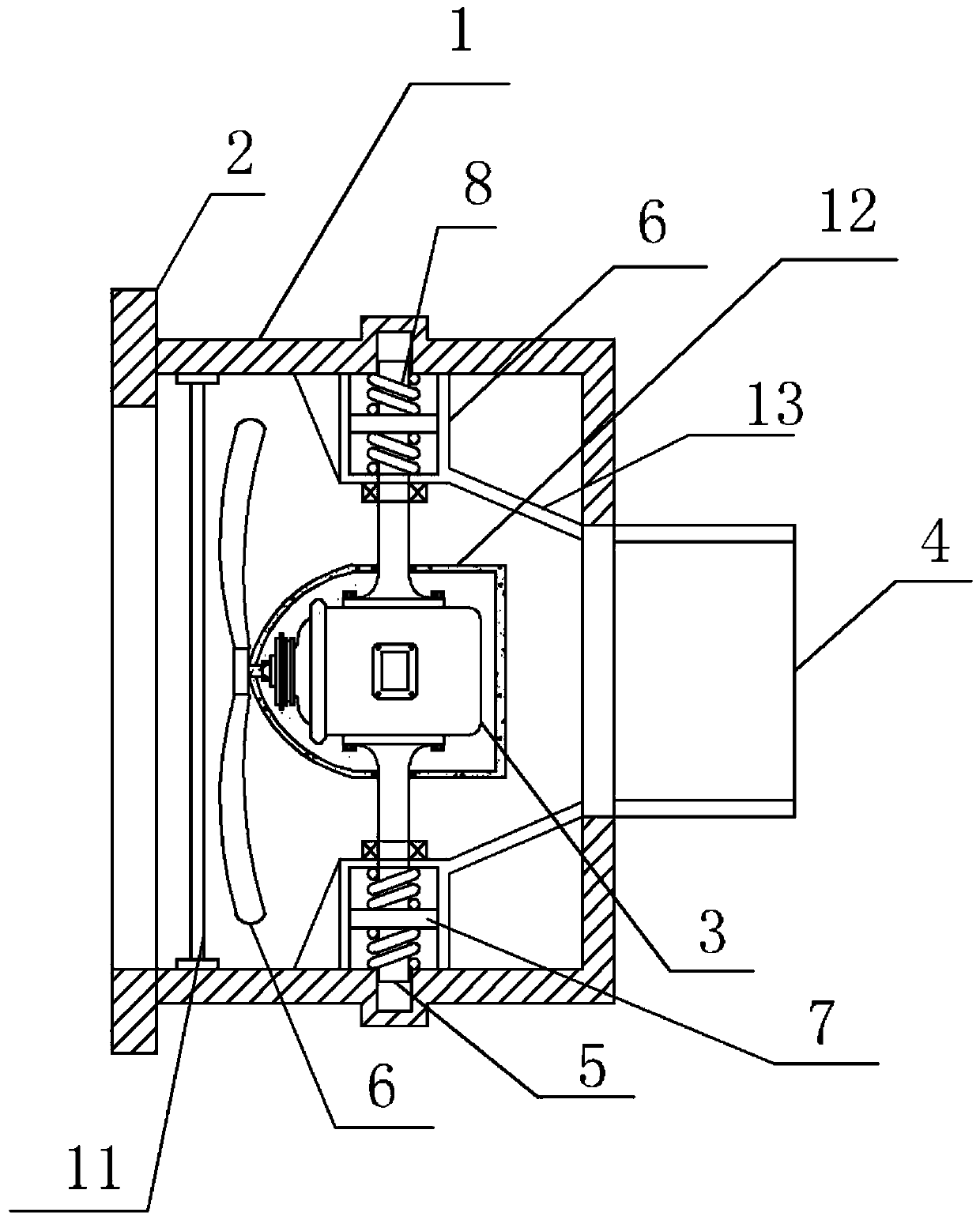
[0019] A front-end air intake device for oil fume treatment in this embodiment, such as figure 1 As shown, it includes a housing 1 with an opening A on one side and an air intake cover 2 arranged at the opening A of the housing 1. The housing 1 is provided with a fan 3 facing the opening A. The housing 1 An exhaust port 4 is provided on the side away from the opening A; both sides of the fan 3 are movably connected with the housing 1 through a damping device arranged on the inner wall of the housing 1; the damping device is fixedly connected with the fan 3 The connecting rod 5 is composed of a shock absorbing cylinder 6 fixed on the inner wall of the housing 1. The end of the connecting rod 5 away from the fan 3 is inserted into the shock absorbing cylinder 6 and reciprocates along the axial direction in the shock absorbing cylinder 6; the connecting rod 5 is inserted into the One end is provided with a circular baffle 7 perpendicular to the connecting rod 5, the curved side w...

Embodiment 3

[0022] This embodiment is further defined on the basis of the above embodiments, the casing 1 is provided with a metal mesh filter layer 11 for filtering between the opening A and the fan 3 . The outside of the fan 3 is provided with an oil-proof shell 12 that completely wraps the fan 3 . One side of the opening B is provided with a conical shroud 13 . The shell 1 is provided with a sound-insulating sponge layer on the outside. Other parts of this embodiment are the same as those of the foregoing embodiment, and will not be repeated here.


PUM


Abstract

The invention discloses a front-end air inlet device for treating lampblack. The front-end air inlet device comprises a casing and an air inlet cover, wherein an opening A is formed in one side of thecasing; the air inlet cover is arranged at the opening A of the casing; a fan just opposite to the opening A is arranged in the casing; an exhaust opening is formed in one side, away from the openingA, of the casing; two sides of the fan are movably connected with the casing through damping devices arranged on the inner wall of the casing; each damping device consists of a connecting rod which is fixedly connected with the fan and a damping cylinder fixed on the inner wall of the casing; one end, away from the fan, of each connecting rod, is inserted into the corresponding damping cylinder and does reciprocating motion in the corresponding damping cylinder along the axial direction; a circular separation blade perpendicular to each connecting rod is arranged at the end part of the inserting end of the connecting rod; the curved side wall of each circular separation blade makes contact with the inner wall of the corresponding damping cylinder; springs fixed on the inner walls of the damping cylinders are respectively arranged on the surfaces of the upper and lower sides of the circular separation blades; a buffer force is provided for reciprocating motion of the connecting rods bythe springs arranged on the upper and lower sides of the circular separation blades. The front-end air inlet device disclosed by the invention is simple in structure and capable of reducing noise.

Description

technical field [0001] The invention relates to the field of oil fume treatment equipment, and specifically refers to a front-end air intake device for oil fume treatment. Background technique [0002] Kitchen fume is a large amount of thermal oxidation decomposition products produced by cooking oil and food under high temperature conditions. When cooking, the fat is heated. When the temperature reaches the smoking point of edible oil at 170°C, the blue smoke of initial decomposition appears. As the temperature continues to rise, the decomposition speed accelerates. There is a pungent smell, and the particle size of oil fume is 0.01-0.3 microns. The oil fume samples collected from households that often fry food were analyzed, and a total of more than 220 chemical substances were detected, including aldehydes, ketones, hydrocarbons, fatty acids, alcohols, aromatic compounds, esters, lactones, heterocyclic compounds, etc. . Known mutational carcinogens such as volatile nitr...

Claims


Application Information

Patent Timeline
IPC IPC(8): F24C15/20
Inventor 何金蓉
Owner 成都蓝吉星科技有限公司
Learn More