
Electric energy generating photo-thermal trough collector

A collector and trough technology, applied in the field of trough solar thermal collectors, can solve problems such as insufficient utilization of solar energy

Pending Publication Date: 2018-01-30
SOUTHEAST UNIV +1
View PDF6 Cites 2 Cited by
  • Summary
  • Abstract
  • Description
  • Claims
  • Application Information

AI Technical Summary

Problems solved by technology

In the existing trough-type trough-type photothermal collectors, only the single use of sunlight can be converted into heat energy, and the solar energy cannot be fully utilized.

Method used


Image

  • Electric energy generating photo-thermal trough collector
  • Electric energy generating photo-thermal trough collector
  • Electric energy generating photo-thermal trough collector

Examples


Embodiment Construction

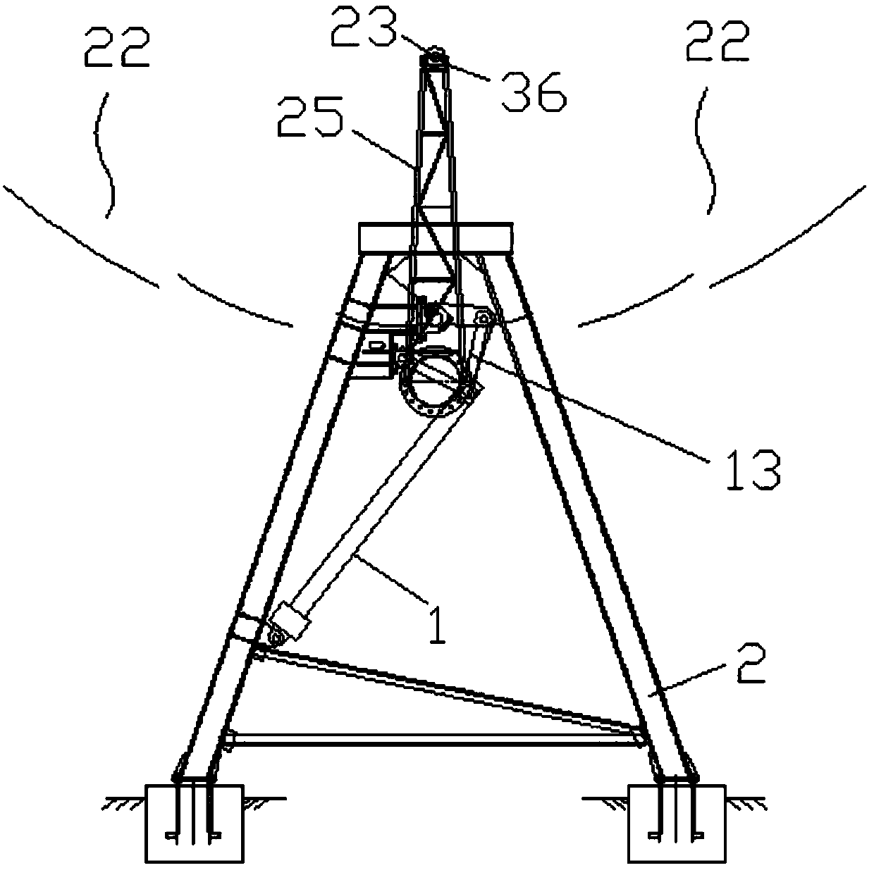
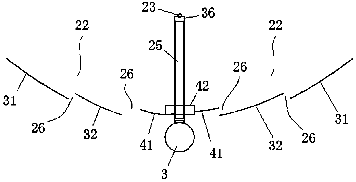
[0024] Depend on Figure 1-Figure 15 The trough photothermal collector that can produce electric energy is shown, and the trough photothermal collector is also called a trough solar collector, including a torsion tube 3 arranged on the bottom bracket, and the upper side of the torsion tube 3 is fixed The heat collecting tube support 25, the heat collecting tube 23 is arranged on the upper side of the heat collecting tube support 25, and the heat collecting tube 23 and the torsion tube 3 are horizontally arranged horizontally on the left and right sides;

[0025] The specific structure of the trough photothermal collector 21 is as follows:

[0026] It includes two bottom brackets 2 arranged at intervals on the left and right, two linkage mechanisms 13 respectively arranged on the two bottom brackets 2, a horizontally arranged torsion tube 3 and a vertically arranged electric push rod 1, the torsion tube 3 A heat collecting tube bracket 25, a reflector group 22 and a signal pla...


PUM


Abstract

The invention belongs to the field of photo-thermal techniques and discloses an electric energy generating photo-thermal trough collector. Thermal collecting tube supports are arranged outside torsiontubes which are arranged on bottom supports, thermal collecting tubes are arranged on the thermal collecting tube supports, the thermal collecting tubes and the torsion tubes are arranged transversely, and reflector groups are arranged on two sides of the thermal collecting tubes of the photo-thermal trough collector. The multiple thermal collecting tube supports are longitudinally and sequentially arranged at intervals along the torsion tubes, and a solar photovoltaic panel is arranged between every two adjacent thermal collecting tube supports. The photo-thermal trough collector further comprises a cleaning device and is capable of generating electric energy by adoption of the photovoltaic technology.

Description

technical field [0001] The invention belongs to the field of photothermal technology, and in particular relates to a trough-type photothermal collector capable of generating electric energy. Background technique [0002] The energy of the sun is divided into solar heat radiation capacity and photon energy. In the existing trough-type trough-type photothermal heat collectors, only sunlight can be converted into heat energy, and solar energy cannot be fully utilized. Contents of the invention [0003] The purpose of the present invention is to provide a trough photothermal collector that can generate electric energy using photovoltaic technology. [0004] In order to achieve the above object, the present invention adopts the following technical scheme: a trough-type photothermal heat collector capable of producing electric energy, including a torsion tube arranged on the bottom bracket, a heat collection tube support is arranged outside the torsion tube, and a heat collecti...

Claims


Application Information

Patent Timeline
IPC IPC(8): F24S23/70F24S40/20H02S10/30H02S40/10
CPCY02E10/40Y02E10/50
Inventor 陈九法王楠张跃兵郭剑峰
Owner SOUTHEAST UNIV
Learn More