
Building supporting structure applied to foundation pit terrain and realizing method of structure

A technology for supporting structures and buildings, which is applied in basic structure engineering, construction, excavation, etc., can solve the problems of insufficient lateral rigidity, reinforcement treatment with bolts, and poor support, so as to improve lateral rigidity and support, Satisfy the supporting performance and maintain the stable effect

Active Publication Date: 2018-02-02
GUANGDONG UNIV OF TECH
View PDF3 Cites 4 Cited by
  • Summary
  • Abstract
  • Description
  • Claims
  • Application Information

AI Technical Summary

Problems solved by technology

Since the pile foundation plays a major role in supporting the building, the pile foundation cannot be reinforced with anchor rods. If this operation will weaken the support strength of the pile foundation; when using bored piles or cement mixing piles alone as support piles , there will be problems of insufficient lateral stiffness and poor support. Since one side of the support pile is close to the pile foundation of the building, and the other side is close to the foundation pit, the support pile cannot be reinforced with anchor rods. If this operation will Weaken the support strength of the support piles, so the general support pile structure cannot better meet the support performance, and will cause greater displacement between the soil and the support piles and pile foundations, resulting in support piles and piles The foundation cannot be used normally, thereby endangering the stability of the building, which will lead to the collapse of the building

Method used


Image

  • Building supporting structure applied to foundation pit terrain and realizing method of structure
  • Building supporting structure applied to foundation pit terrain and realizing method of structure

Examples


Embodiment Construction

[0026] The present invention will be further described in detail below in conjunction with the embodiments and the accompanying drawings, but the embodiments of the present invention are not limited thereto.

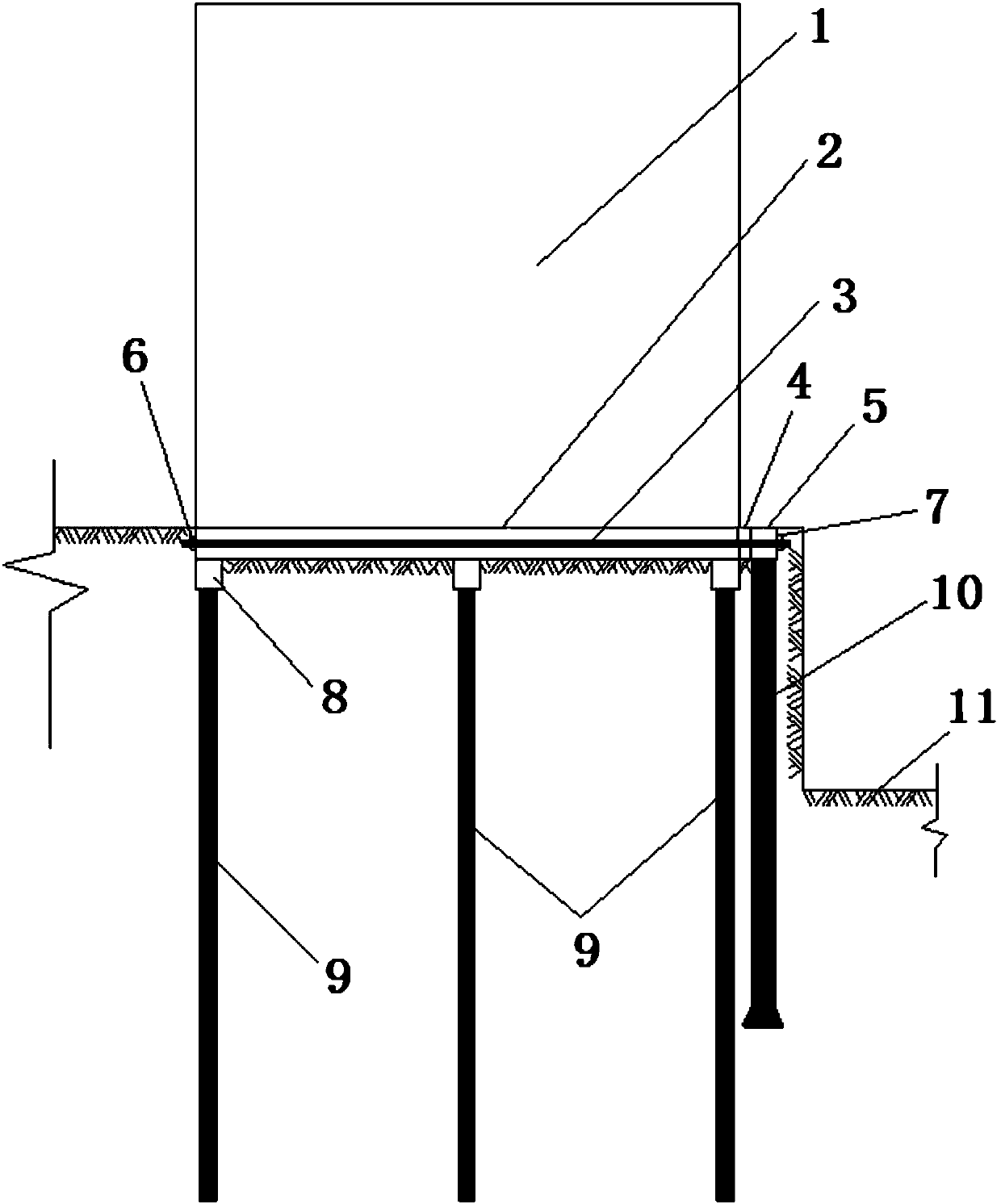
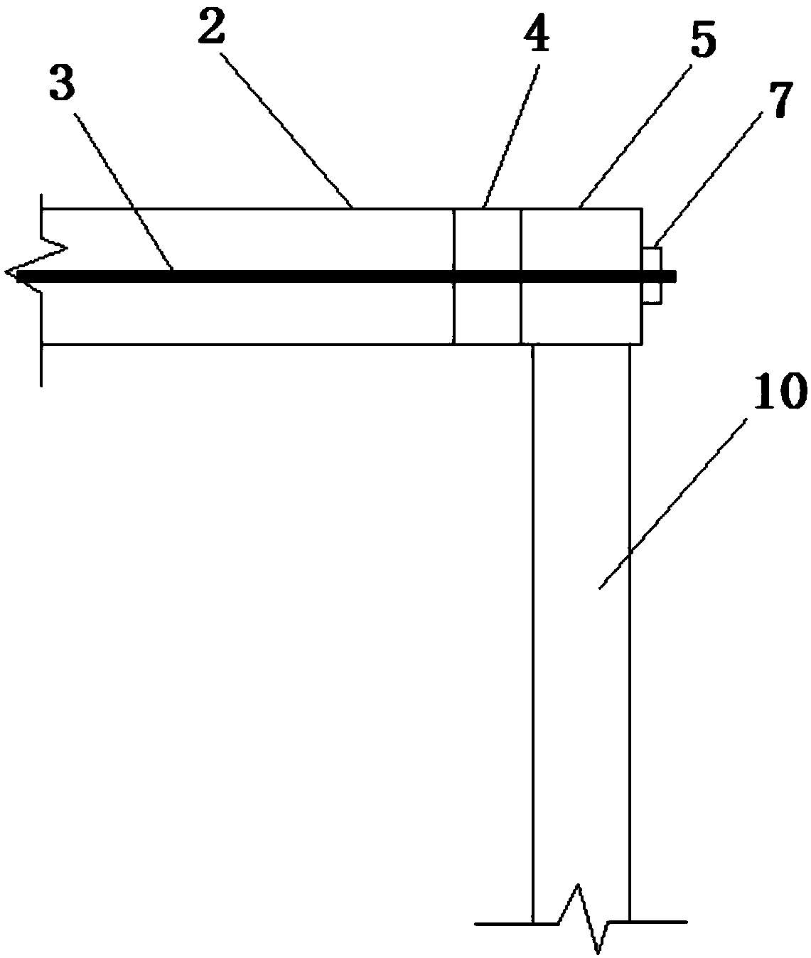
[0027] Such as Figure 1~2 As shown, a building support structure applied to foundation pit terrain includes a building 1 located on the left side of the foundation pit 11. The building 1 is a place for human activities or available for use. The building 1 Set on the ground, and the concrete base plate 2, cap platform 8, pile foundation 9, unbonded prestressed anchor cable 3, crown beam 5, metal cover plate 4, first anchor cable located under the building 1 and arranged underground An anchor head 6, a second anchor cable anchor head 7 and a support pile 10, wherein the concrete floor 2 is connected to the building 1, and the pile foundation 9 is connected to the concrete floor 2 through the cap 8 Connected, the caps 8 and pile foundations 9 are provided in multiples, an...


PUM


Abstract

The invention discloses a building supporting structure applied to the foundation pit terrain. The structure comprises a building located on the left side of a foundation pit as well as a concrete bottom plate, bearing platforms, pile foundations, non-sticky pre-stressed anchor cables, a crown beam, a metal cover plate, a first anchor cable anchor head, a second anchor cable anchor head and a supporting pile which are located below the building and arranged underground; the building is arranged above the ground; the concrete bottom plate is connected with the building; the pile foundation is connected with the concrete bottom plate through the bearing platforms; and the multiple bearing platforms and the multiple pile foundations support the concrete bottom plate and the building above theconcrete bottom plate. Compared with general cast-in-place piles, the structure of the non-sticky pre-stressed anchor cables, the crown beam and the supporting pile has the advantages that the lateral stiffness and the supporting performance of the supporting pile which cannot realize anchor rod driving are improved, and the supporting performance of the supporting structure is better met.

Description

technical field [0001] The invention relates to the technical field of building support, in particular to a building support structure applied to foundation pit topography and an implementation method thereof. Background technique [0002] At present, the supporting structure of multi-storey buildings is mainly based on bored piles or cement mixing piles. According to the requirements of design and construction, it is necessary to build multi-storey buildings near the topography of the foundation pit, and the self-weight of the buildings Under the action, the support piles near the side of the foundation pit bear greater soil lateral pressure. Since the pile foundation plays a major role in supporting the building, the pile foundation cannot be reinforced with anchor rods. If this operation will weaken the support strength of the pile foundation; when using bored piles or cement mixing piles alone as support piles , there will be problems of insufficient lateral stiffness a...

Claims


Application Information

Patent Timeline
Patent Type & Authority Applications(China)
IPC IPC(8): E02D17/04E02D5/44E02D27/12E02D5/74
CPCE02D5/44E02D5/74E02D17/04E02D27/12
Inventor 房采杏梁仕华曾伟华
Owner GUANGDONG UNIV OF TECH
Learn More