
Rolling bearing with flange

A technology for rolling bearings and mounting flanges, which is applied to rolling contact bearings, roller bearings, bearings for rotational motion, etc., and can solve problems such as outer ring inclination, unfavorable safe operation, and shortened service life

Active Publication Date: 2018-02-02
AB SKF
View PDF7 Cites 0 Cited by
  • Summary
  • Abstract
  • Description
  • Claims
  • Application Information

AI Technical Summary

Problems solved by technology

Due to this non-uniform heat distribution in the outer ring, the outer ring may tilt due to the large radial extension of the non-fixed side
As a result, there is no longer a uniform load of the two rolling element rows, which is detrimental to safe operation and shortens the service life

Method used


Image

  • Rolling bearing with flange

Examples


Embodiment Construction

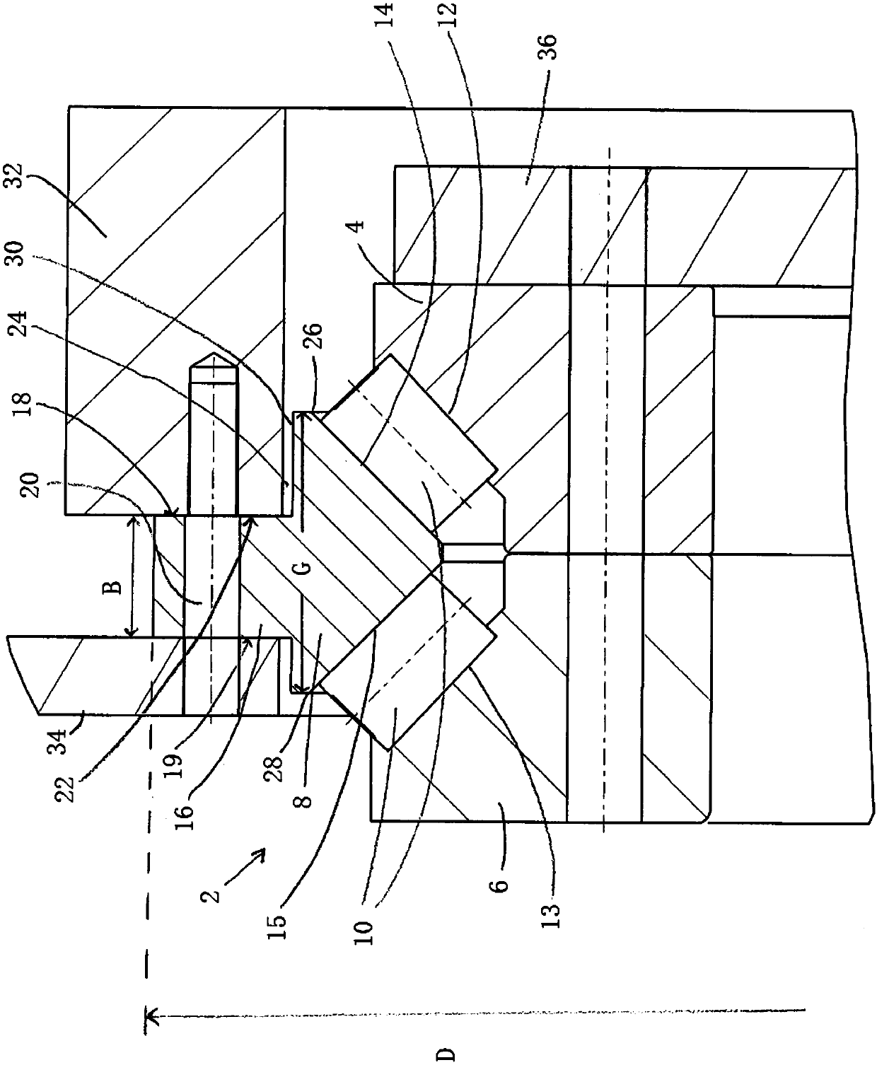
[0046] figure 1 Shown is a rolling bearing 2 which is designed as a double-row tapered roller bearing. The outer ring 8 is configured as one-part and includes a first raceway 14 and a second raceway 15 . The inner ring is composed of a first inner ring 4 and a second inner ring 6. Here, the first inner ring 4 includes a first raceway 12 and the second inner ring 6 includes a second raceway 13 . Two rolling element rows 10 roll between the raceways of the outer ring and the raceways of the inner ring. Here, the individual rolling element rows 10 consist of rolling elements arranged in the circumferential direction, wherein the rolling elements are configured as frusto-conical rolling elements.

[0047] The two raceways of the outer rings are inclined at an angle with respect to the axis of rotation of the rolling bearing and each raceway of the outer ring comprises an outer axial end 26,28. Here "outer axial end" is understood to mean the end of the surface formed by the an...


PUM


Abstract

A rolling bearing comprising at least one inner ring, at least one outer ring and two rows of rolling elements, the two rolling elements being arranged on at least one inner ring of first and second raceways and at least one outer ring rolling between the first raceway and the second raceway, wherein the inner ring or the outer ring is configured as a portion and includes a radially extending integral mounting flange, and the mounting flange comprises a first axial abutting surface which extends radially. In the mounting flange, an axially extending through hole is provided for axially attaching the inner ring or the outer ring to the radially opposite abutting surface, including the inner ring of the mounting flange. The outer ring includes a shoulder on the side of the first axial abutment surface.

Description

technical field [0001] The present invention relates to the double-row rolling (body) bearing according to technical solution 1 and a wind turbine including the rolling bearing. Background technique [0002] Known double row rolling (body) bearings comprise a common bearing ring for the two rows of rolling elements as well as two separate bearing rings for the two rows of rolling elements. For example, a double-row tapered roller bearing is known from DE 10 2009 014 923 A1, which comprises a partial outer ring with two raceways. The opposing raceways are constructed in two parts, and each inner ring includes an inner raceway. Two rows of rolling elements consisting of frusto-conical shaped rolling elements roll between the raceways of the inner ring and the corresponding raceways of the outer ring. In the radially outer region of the raceway, the outer ring comprises a through-hole, with which the outer ring can be screwed onto a machine component (such as a seat). Disadv...

Claims


Application Information

Patent Timeline
IPC IPC(8): F16C19/38F16C33/58
CPCF16C19/38F16C33/585F16C35/063F16C35/067F16C33/586F16C33/60F16C2240/40F16C2240/70F16C2300/14F16C2226/60F03D80/70F16C19/386F16C2360/31Y02E10/72F16C33/583F16C35/045
Inventor 乔纳斯·克里斯滕森马茨·佩尔森彼得·施布纳杰思科-亨宁·塔克
Owner AB SKF
Learn More