
Gas turbine waste heat boiler

A waste heat boiler and gas turbine technology, applied in steam boilers, steam boiler accessories, steam boiler components, etc., can solve the problems of long maintenance time, inconvenient maintenance operation, and affecting work efficiency.

Pending Publication Date: 2018-02-02
SUZHOU HAILU HEAVY IND
View PDF8 Cites 0 Cited by
  • Summary
  • Abstract
  • Description
  • Claims
  • Application Information

AI Technical Summary

Problems solved by technology

The disadvantages of the currently used gas turbine waste heat boilers are: during the use of the gas turbine waste heat boilers, it is unavoidable Leakage will occur. When the middle heat exchange tube bundle in the heat exchange tube bundle group leaks, the tube bundle can only be cut row by row from the outermost heat exchange tube bundle in the heat exchange tube bundle group until it reaches the leakage of the middle heat exchange tube bundle. After repairing the leak point or replacing the pipes, the cut pipe bundles are restored row by row from the middle to the outside. The whole maintenance process takes at least 3 days. The maintenance operation is inconvenient and time-consuming, which greatly affects the work efficiency

Method used


Image

  • Gas turbine waste heat boiler
  • Gas turbine waste heat boiler
  • Gas turbine waste heat boiler

Examples


Embodiment Construction

[0011] The present invention will be further described below in conjunction with the accompanying drawings and specific embodiments.

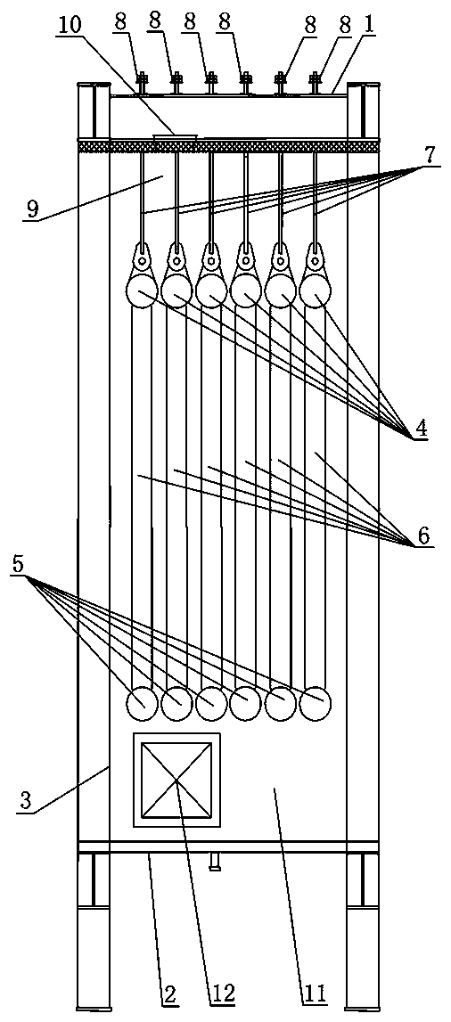
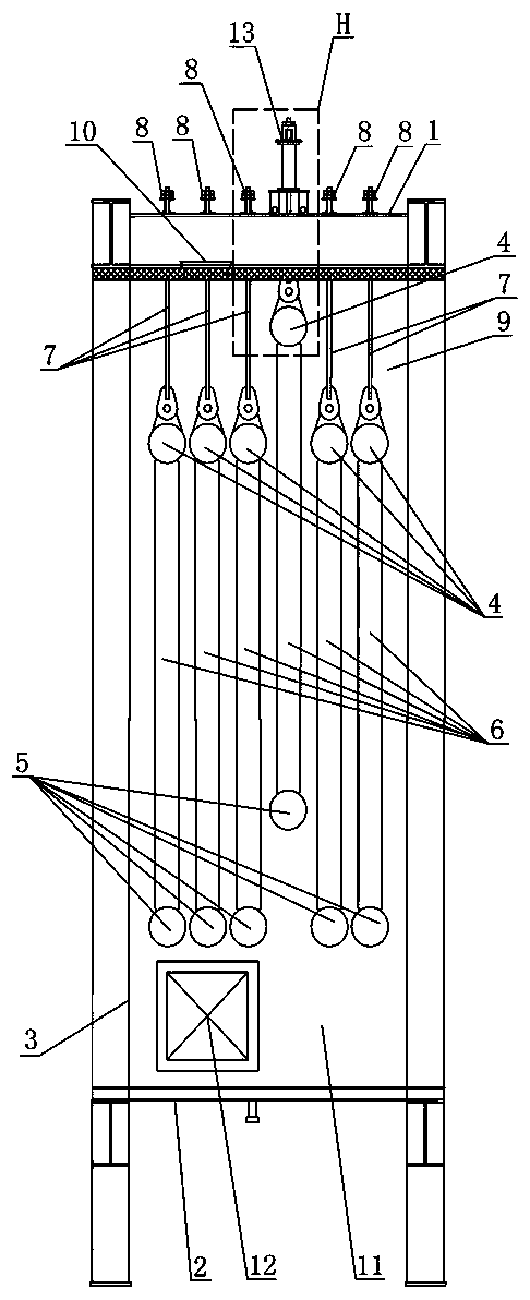
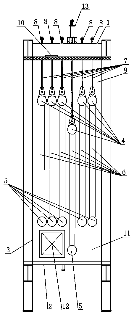
[0012] like figure 1 , figure 2 , image 3 , Figure 4 As shown, the gas turbine waste heat boiler includes a boiler shell surrounded by a top plate 1, a bottom plate 2 and a side plate 3, and a heat exchange tube bundle group is arranged inside the boiler shell, and the heat exchange tube bundle group consists of several Each row of heat exchange tube bundles includes an upper header 4, a lower header 5, and a number of heat exchange tubes 6 connecting the upper header 4 and the lower header 5. A long threaded suspender 7 is installed vertically at the left and right ends of the top of the upper header 4 of each row of heat exchange tube bundles. There are two fastening nuts 8 connected, and each row of heat exchange tube bundles is movably hung on the top plate 1 of the boiler shell through the cooperation of the fastening nuts 8 and the...


PUM


Abstract

The invention discloses a gas turbine waste heat boiler. The gas turbine waste heat boiler comprises a boiler shell defined by a top plate, a bottom plate and a side plate; a plurality of rows of heatexchanging pipe bundles sequentially arranged at intervals in the flue gas flowing direction are arranged in the boiler shell to form a heat exchanging pipe bundle set; each row of heat exchanging pipe bundles comprise an upper header, a lower header and heat exchanging pipes; the left end and the right end of the top of the upper header of each row of heat exchanging pipe bundles are each provided with a long threaded hoisting rod; the upper end of each long threaded hoisting rod movably and upwardly penetrates the top plate and then is connected with a fastening nut; each row of heat exchanging pipe bundles are matched with the corresponding long threaded hoisting rods through the corresponding fastening nuts to be movably hoisted and hung on the top plate; an overhauling space is reserved between the heat exchanging pipe bundle set and the top plate as well as between the heat exchanging pipe bundle set and the bottom plate; a first man hole is formed in the top plate of the boilershell; and a second man hole is formed in the lower portion of the side plate of the boiler shell. The gas turbine waste heat boiler has the beneficial effects that overhauling operation is convenient and time consumed for overhauling is short.

Description

technical field [0001] The invention relates to the technical field of boilers, in particular to a gas turbine waste heat boiler. Background technique [0002] Gas turbine waste heat boiler is a kind of waste heat boiler commonly used at present, which is mainly used for waste heat recovery of high temperature flue gas with flue gas temperature of 500 ℃ ~ 600 ℃. The structure of the currently used gas turbine waste heat boiler is: a boiler shell surrounded by a top plate, a bottom plate and a side plate, and a heat exchange tube bundle group is fixed inside the boiler shell. The gas flow direction is composed of heat exchange tube bundles arranged at intervals in sequence, and each row of heat exchange tube bundles includes: an upper header and a lower header fixed on the boiler shell, and a number of heat exchange tubes connecting the upper header and the lower header. The disadvantages of the currently used gas turbine waste heat boilers are: during the use of the gas tur...

Claims


Application Information

Patent Timeline
IPC IPC(8): F22B31/00F22B37/02
CPCF22B31/00F22B37/02
Inventor 葛卫东钱飞舟滕志英
Owner SUZHOU HAILU HEAVY IND
Learn More