Connector

A technology for connectors and soldering parts, which is applied in the direction of connection, fixed connection, conductive connection, etc., and can solve problems such as assembly errors, inability to perform reflow soldering process steps, and poor soldering effect of connector circuit boards.

Active Publication Date: 2018-02-02
DEYI PRECISION ELECTRONIC IND CO LTD PANYU
View PDF6 Cites 8 Cited by
  • Summary
  • Abstract
  • Description
  • Claims
  • Application Information

AI Technical Summary

Problems solved by technology

[0003] The above-mentioned connector welded to the circuit board in a surface mount manner, due to manufacturing errors of the terminals, and after the terminals are assembled in the insulating body, the first welding part and the second welding part There is an assembly error in the part, so that the lowest point of the first welding part and the lowest point of the second welding part are uneven, but when the second welding part in the inner row is lower than the first welding part in the outer row Welding part, when the connector is placed on the circuit board, the second welding part abuts against the circuit board first, so that the inner two rows of the second welding parts are positioned on the circuit board as support points On the board, especially the connector is a slender structure, and four rows of the welding parts are arranged on a narrow width, and the distance between the inner two rows of the second welding parts in the width direction is relatively close, so The connector is easy to tilt or fall to one side in the width direction, so that the soldering effect between the connector and the circuit board is not good, or the subsequent reflow process steps cannot be performed

Method used


Image

  • Connector
  • Connector
  • Connector

Examples


Embodiment Construction

[0040] In order to facilitate a better understanding of the purpose, structure, features, and effects of the present invention, the present invention will now be further described in conjunction with the accompanying drawings and specific embodiments.

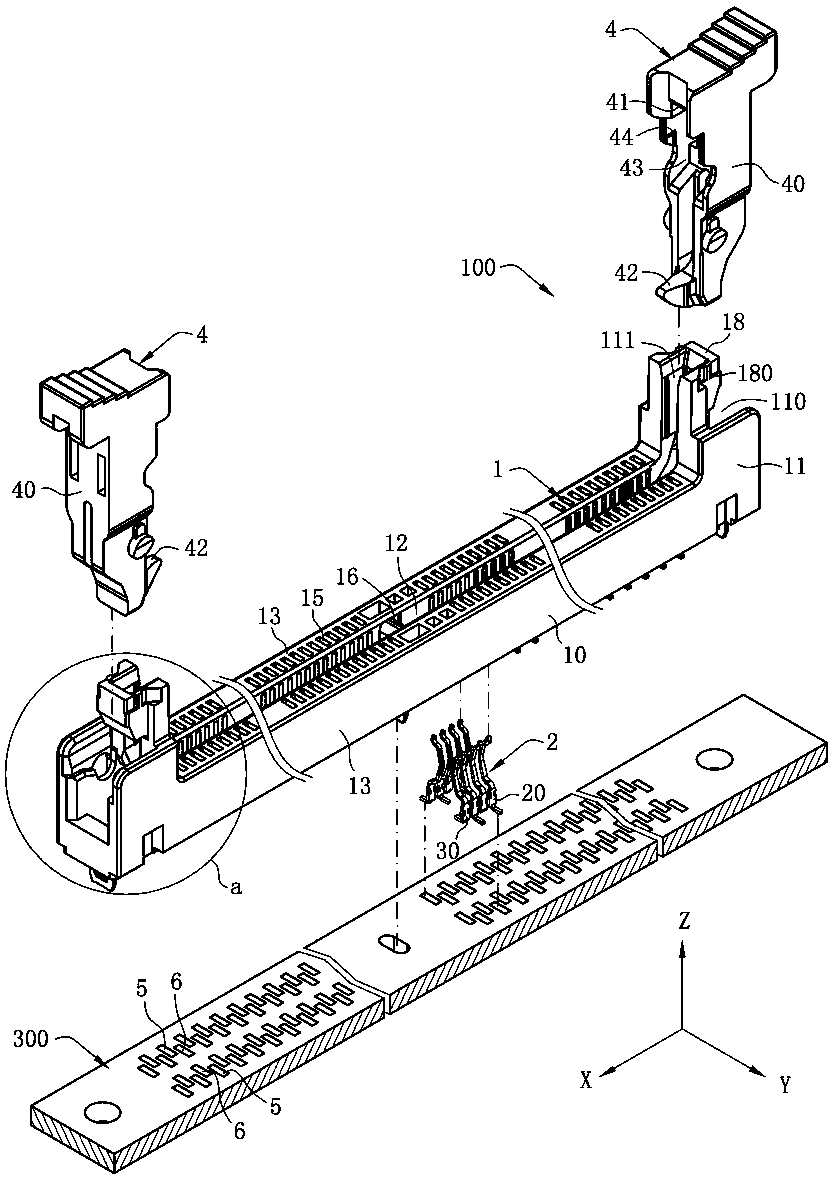
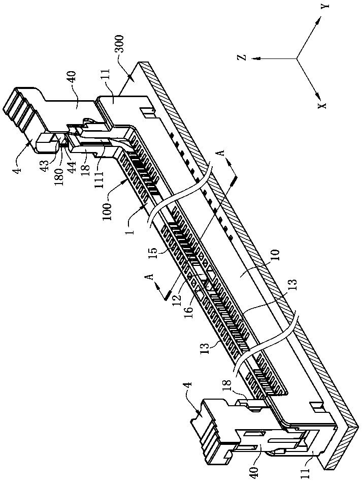
[0041] see figure 1 and Image 6 , is a connector 100 of the present invention, used to electrically connect the electronic card 200 and the circuit board 300, the connector 100 is installed downward on the circuit board 300, and the connector 100 includes an insulating body 1, A plurality of terminals 2 disposed on the insulating body 1 and two ear buckles 4 pivotally connected to the insulating body 1 . The connector 100 defines a longitudinal direction X, a lateral direction Y, and a vertical direction Z, and the three are perpendicular to each other.

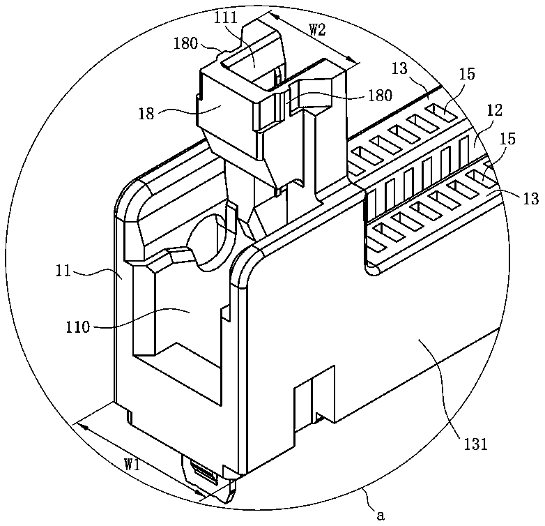
[0042] see figure 1 , figure 2 and Image 6, the bottom surface of the insulating body 1 is set facing the circuit board 300 . The insulating body 1 has a base portion...


PUM


Abstract

The invention discloses a connector, which is used for being arranged on a circuit board and comprises an insulating body, a plurality of first terminals and a plurality of second terminals, wherein the bottom surface of the insulating body is opposite to the circuit board; each first terminal is provided with a first fixed part fixedly arranged on the insulating body and a first welding part which extends from the first fixed part in a bending manner and is exposed out of the bottom surface of the insulating body; each second terminal is provided with a second fixed part fixedly arranged on the insulating body and a second welding part which extends from the second fixed part in a bending manner and is exposed out of the bottom surface of the insulating body; the first welding parts and the second welding parts are welded on the circuit board in a surface mounting manner; the plurality of first welding parts and the plurality of second welding parts are arranged in four rows in the transverse direction; the plurality of first welding parts are distributed in the external two rows; the plurality of second welding parts are distributed in the internal two rows; the bottom surface ofeach first welding part is provided with a lowest point; a plane is defined by the lowest points of the first welding parts in the external two rows; and the second welding parts are located at the upper part of the plane. The condition that the connector is steadily put on the circuit board and the phenomenon of inclining or dumping towards one side does not easily occur is ensured.

Description

technical field [0001] The invention relates to a connector, in particular to a connector for inserting an electronic card. Background technique [0002] A conventional connector is used for mounting on a circuit board. The connector includes an insulating body and a plurality of terminals assembled on the insulating body. The bottom surface of the insulating body faces the circuit board. Each of the terminals has a fixing portion fixed on the insulating body and a welding portion exposing the bottom surface of the insulating body, the plurality of welding portions are arranged in four rows, and the plurality of welding portions include a plurality of first A welded portion and a plurality of second welded portions, wherein the plurality of first welded portions are distributed in two outer rows, and the plurality of second welded portions are distributed in two inner rows. [0003] The above-mentioned connector welded to the circuit board in a surface mount manner, due to ...

Claims


Application Information

Patent Timeline
Patent Type & Authority Applications(China)
IPC IPC(8): H01R12/57H01R12/72H01R12/73H01R13/02H01R13/46
CPCH01R12/57H01R12/721H01R12/737H01R13/02H01R13/46H01R12/716H01R4/027H01R13/62938
Inventor 朱德祥蔡友华
Owner DEYI PRECISION ELECTRONIC IND CO LTD PANYU
Why Eureka
Try Eureka