
U-shaped coaxial RF connector and assembling method thereof

A technology of radio frequency connectors and assembly methods, which is applied to two-part connection devices, parts of connection devices, connections, etc., can solve problems such as increased costs, test line performance errors, and loss of test line life, and achieve increased costs. , the effect of simple method

Pending Publication Date: 2018-02-02
EZCON TELECOM TECHCHANGZHOU
View PDF0 Cites 1 Cited by
  • Summary
  • Abstract
  • Description
  • Claims
  • Application Information

AI Technical Summary

Problems solved by technology

[0002] At present, ordinary RF connectors usually have a two-end straight structure, which is applied to the dual-channel calibration connection port on the test instrument. The conventional dual-channel calibration uses a method of connecting a test line to one port, and this method is more accurate. Frequent testing over time will not only reduce the life of the test line and increase the cost, but also the performance error of the test line will cause inaccurate test results

Method used


Image

  • U-shaped coaxial RF connector and assembling method thereof
  • U-shaped coaxial RF connector and assembling method thereof
  • U-shaped coaxial RF connector and assembling method thereof

Examples


Embodiment Construction

[0027] In order to make the content of the present invention more clearly understood, the present invention will be further described in detail below based on specific embodiments and in conjunction with the accompanying drawings.

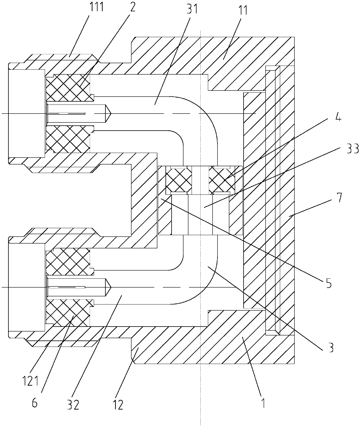
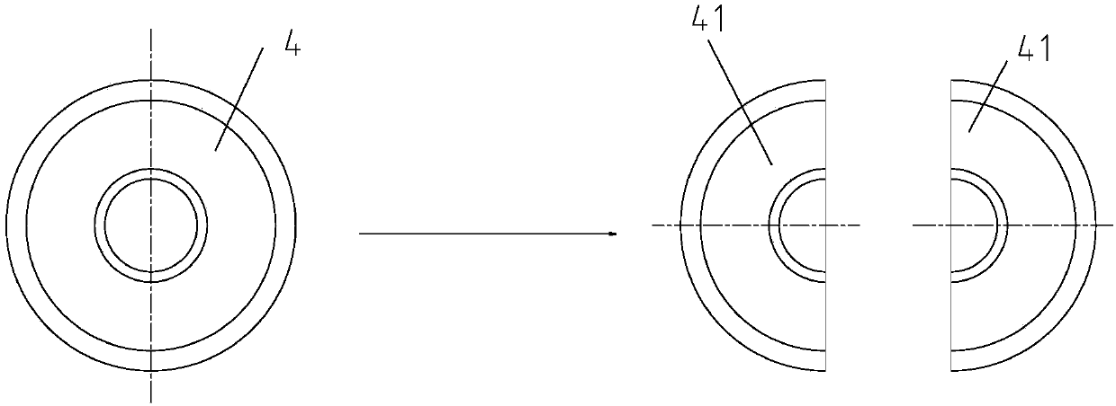
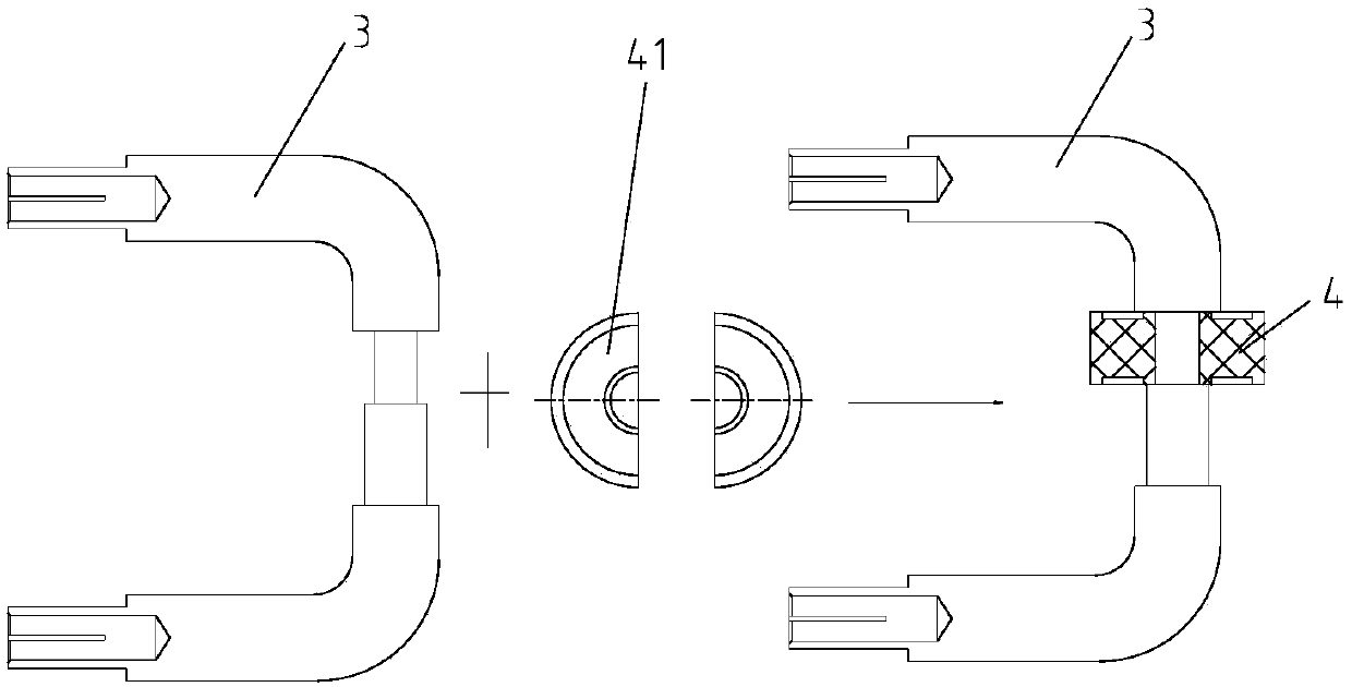
[0028] like figure 1 As shown, a U-shaped coaxial RF connector, which includes:

[0029] A casing 1, the casing 1 has an upper casing part 11 and a lower casing part 12, the upper casing part 11 is located above the lower casing part 12, and the rear part of the casing 1 is provided with an assembly hole;

[0030] Pin 3, the pin 3 is a U-shaped structure, and the pin 3 has an upper pin 31, a lower pin 32, and a middle transition for connecting the upper pin 31 and the lower pin 32 part 33, the upper insulator 2 is supported on the upper pin 31, the upper insulator 2 is press-fitted in the upper shell part 11, the upper pin 31 is accommodated in the upper shell part 11, and the The upper pin 31 is separated from the upper shell part 11, the lower ...


PUM


Abstract

The invention discloses a U-shaped coaxial RF connector and an assembling method thereof. The U-shaped coaxial connector comprises a housing, a pin, an outer conductor and a cover board. The housing comprises an upper housing and a lower housing. The upper housing is arranged above the lower housing. The back part of the housing is provided with an assembling hole. The pin has a U-shaped structure. Furthermore the pin is provided with an upper pin, a lower pin and a middle transition part for connecting the upper pin with the lower pin. The upper pin supports an upper insulator. The upper insulator is compressed in the upper housing. The upper pin is accommodated in the upper housing. Furthermore the upper pin is separated from the upper housing. The lower pin supports a lower insulator. The lower insulator is compressed in the lower housing. The lower pin is accommodated in the lower housing. Furthermore the lower pin is separated from the lower housing. The middle transition part supports a middle insulator. The U-shaped coaxial RF connector can be directly connected with a double-channel calibrating communicating port on a testing instrument, thereby improving testing accuracy,preventing service reduction of a testing wire and reducing testing cost.

Description

technical field [0001] The invention relates to a U-shaped coaxial radio frequency connector and an assembly method thereof. Background technique [0002] At present, ordinary RF connectors usually have a two-end straight structure, which is applied to the dual-channel calibration connection port on the test instrument. The conventional dual-channel calibration uses a method of connecting a test line to one port, and this method is more accurate. Frequent testing over time will not only reduce the life of the test line and increase the cost, but also the performance error of the test line will cause inaccurate test results. Contents of the invention [0003] The technical problem to be solved by the present invention is to overcome the defects of the prior art and provide a U-shaped coaxial radio frequency connector, which can be directly connected to the dual-channel calibration communication port on the test instrument, so as to improve the test accuracy and avoid loss o...

Claims


Application Information

Patent Timeline
IPC IPC(8): H01R13/40H01R13/502H01R24/40H01R43/20
CPCH01R13/40H01R13/502H01R24/40H01R43/20
Inventor 刘泽民孙琪宁
Owner EZCON TELECOM TECHCHANGZHOU
Learn More