Full-self-cooling type motor
A technology of self-cooling and air intake device, used in electrical components, electromechanical devices, electric components, etc., can solve problems such as poor heat dissipation, and achieve the effects of low renovation cost, improved heat dissipation capacity, and energy loss saving
- Summary
- Abstract
- Description
- Claims
- Application Information
AI Technical Summary
Problems solved by technology
Method used
Image
Examples
Embodiment 1
[0031] Embodiment 1, taking the motor (motor or generator) of the present invention as an example:
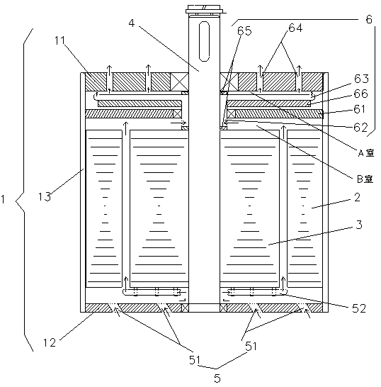
[0032] A fully self-cooling motor, comprising: a casing 1, a stator 2, a rotor 3, a motor shaft 4, an air intake device 5 and an exhaust device 6; the casing 1 includes a front cover 11, a rear end cover 12 and a body shell 13.
[0033] The air intake device 5 is an air intake hole 51 arranged on the rear end cover 12 .
[0034] The exhaust device 6 includes: an isolation plate 61 arranged between the front end cover 11 and the rotor 3 , a sleeve 62 sleeved on the motor shaft 4 between the front end cover 11 and the rotor 3 , and airtightly connected to the front end cover 11 . 11 and the exhaust pipe 63 on the sleeve 62 of the isolation plate 61 and the exhaust hole 64 provided on the front end cover 11; the two ends of the sleeve 62 are fixed on the motor shaft 4 through the sealing ring 65, so that the inside of the motor passes The two spaces separated by the separating p...
Embodiment 2
[0041] Embodiment 2, taking the tubular door rolling machine assembly with built-in motor as an example:
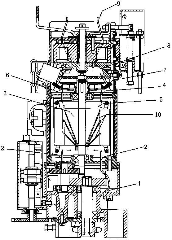
[0042] Such as figure 2 A fully self-cooling motor is shown, including: intake device, collector device and exhaust device.
[0043] The air intake device includes: an air intake hole 1 arranged on the outer contour of the motor, and a hose 2 enabling the motor 5 to communicate with outside air from the air intake hole 1 .
[0044] The collecting device includes: the air outlet of the hose 2 facing the coil 3, the air inlet of the hose 4 facing the coil 3, and the air guide tube 10 arranged inside the coil 3; the air guide tube 10 is close to the air intake The port of the device is arranged at a position close to the electric axis, the other port communicates with the surface of the coil 3, and one or more airway tubes 10 can be provided.
[0045] The space where the motor 5 and the brake disc 6 are only connected through the hose 4, one end of the hose 4 inside the m...
PUM
 Abstract
Description
Claims
Application Information
 - R&D
- Intellectual Property
- Life Sciences
- Materials
- Tech Scout
- Unparalleled Data Quality
- Higher Quality Content
- 60% Fewer Hallucinations
Browse by: Latest US Patents, China's latest patents, Technical Efficacy Thesaurus, Application Domain, Technology Topic, Popular Technical Reports.
© 2025 PatSnap. All rights reserved.Legal|Privacy policy|Modern Slavery Act Transparency Statement|Sitemap|About US| Contact US: help@patsnap.com


