
Camera module

A technology of camera module and driver group, which is applied in the direction of image communication, TV, color TV parts, etc. It can solve the problems of large size and poor stability of the camera module, and achieve small size, high stability, and shortened recovery time. Effect

Active Publication Date: 2018-02-02
NINGBO SUNNY INSTR
View PDF4 Cites 4 Cited by
  • Summary
  • Abstract
  • Description
  • Claims
  • Application Information

AI Technical Summary

Problems solved by technology

[0004] The purpose of the present invention is to provide a camera module to solve the problems of large volume and poor stability of the camera module in the prior art

Method used


Image

  • Camera module
  • Camera module
  • Camera module

Examples


Embodiment Construction

[0080] In order to more clearly describe the embodiments of the present invention or the technical solutions in the prior art, the following will briefly introduce the drawings that are used in the embodiments. Apparently, the drawings in the following description are only some embodiments of the present invention, and those skilled in the art can also obtain other drawings according to these drawings without creative efforts.

[0081] When describing the embodiments of the present invention, the terms "vertical", "transverse", "upper", "lower", "front", "rear", "left", "right", "vertical", " The orientation or positional relationship expressed by "horizontal", "top", "bottom", "inner" and "outer" is based on the orientation or positional relationship shown in the relevant drawings, which are only for the convenience of describing the present invention and simplifying the description, and It is not to indicate or imply that the device or element referred to must have a particu...


PUM

PropertyMeasurementUnit
Thicknessaaaaaaaaaa
Lengthaaaaaaaaaa
Thermal expansion coefficientaaaaaaaaaa

Abstract

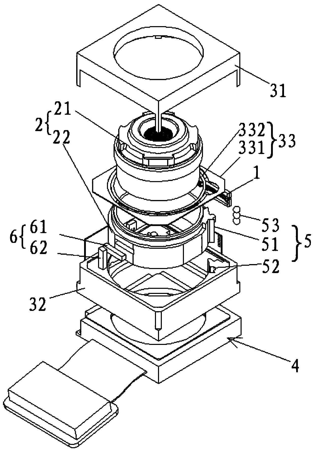
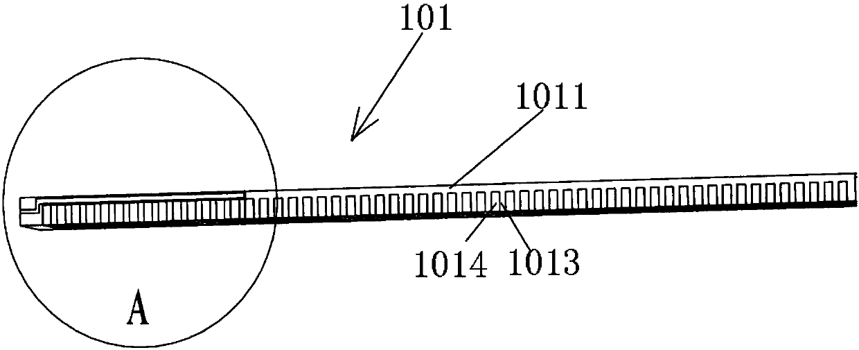
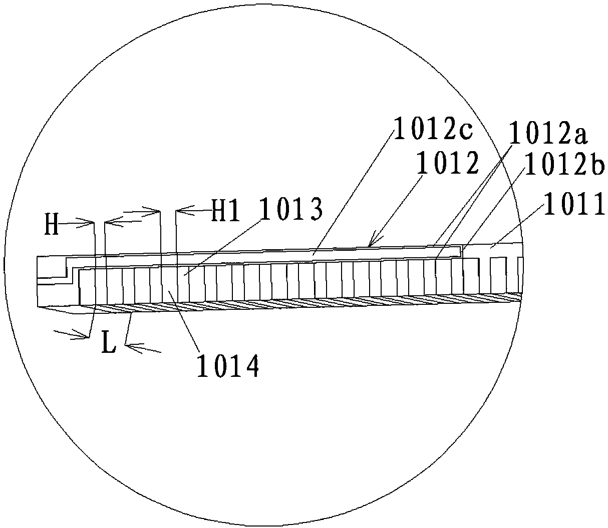
The invention relates to a camera module which comprises a driving device, a lens unit, a supporting unit and an imaging unit. The driving device comprises at least one driver, each driver comprises driving components and a connecting part, the lens unit is arranged in the supporting unit, the supporting unit is arranged on the imaging unit and comprises an upper support and a lower support, and an elastic part is arranged between the lens unit and the upper support. The driving device is arranged between the two opposite side faces of the lens unit and the supporting unit and connected with the lens unit and the supporting unit and can generate driving force to drive the lens unit to do linear motion to achieve focusing of the camera module. According to the camera module, the problems that in the prior art, the thickness of a driving module is limited, the driving stroke is short, and the stability is poor are solved.

Description

technical field [0001] The invention relates to a camera module, in particular to a camera module including an electrothermal driving device. Background technique [0002] In the prior art, VCM motors are widely used in camera modules for automatic focus and automatic image stabilization. Since the current camera system tends to be thinner, has a larger stroke, and lower power, the coil and magnet of the VCM motor hinder the further reduction of the module size. At the same time, VCM motors are based on electromagnetic force, and large strokes require high power support. Therefore, the stroke of the camera module is greatly limited. [0003] In recent years, Shape Memory Alloy (SMA) technology based on the principle of thermal expansion and contraction has been adopted to drive the lens to perform the auto-focus function of the camera lens. However, the shape memory alloy used in the camera module is made of round metal wires, and severe hysteresis and repeated back and f...

Claims


Application Information

Patent Timeline
IPC IPC(8): H04N5/225H04N5/232
CPCH04N23/50H04N23/67H04N23/685H04N23/687
Inventor 张宝忠刘挺张玉文
Owner NINGBO SUNNY INSTR
Learn More