Electronic ballast experiment platform for driving ultraviolet lamp and optimization method of driving power of ultraviolet lamp

A technology for electronic ballasts and ultraviolet lamps, which is applied in the direction of measuring electric power, using electric radiation detectors for photometry, and electrical devices, etc. Power, short life of UV lamps, etc.

Active Publication Date: 2018-02-02
HARBIN INST OF TECH
View PDF1 Cites 0 Cited by
  • Summary
  • Abstract
  • Description
  • Claims
  • Application Information

AI Technical Summary

Problems solved by technology

[0009] The purpose of the present invention is to solve the problems that the existing platforms for calibrating ultraviolet lamps cannot accurately determine the optimal rated power of ultraviolet lamps, resulting in short service life of ultraviolet lamps and low irradiance and light efficiency of short-wave ultraviolet rays. The present invention provides An electronic ballast experimental platform for driving ultraviolet lamps and an optimization method for driving power of ultraviolet lamps

Method used


Image

  • Electronic ballast experiment platform for driving ultraviolet lamp and optimization method of driving power of ultraviolet lamp
  • Electronic ballast experiment platform for driving ultraviolet lamp and optimization method of driving power of ultraviolet lamp
  • Electronic ballast experiment platform for driving ultraviolet lamp and optimization method of driving power of ultraviolet lamp

Examples


specific Embodiment approach 1

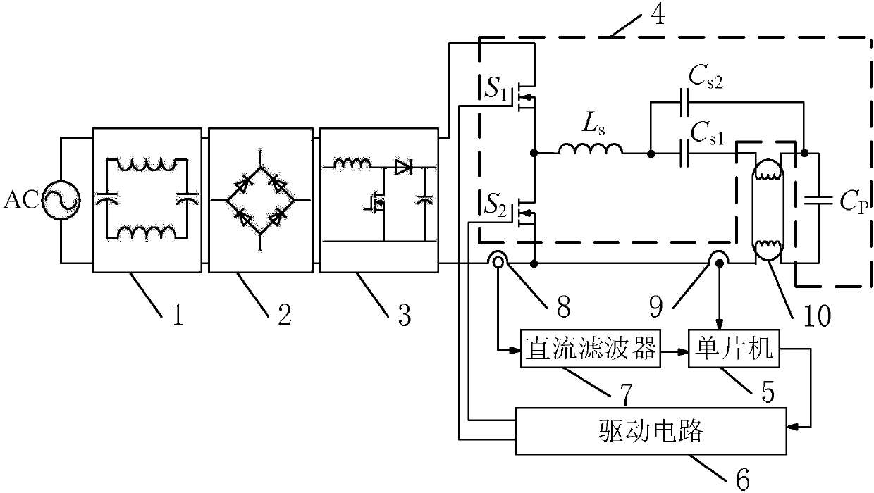
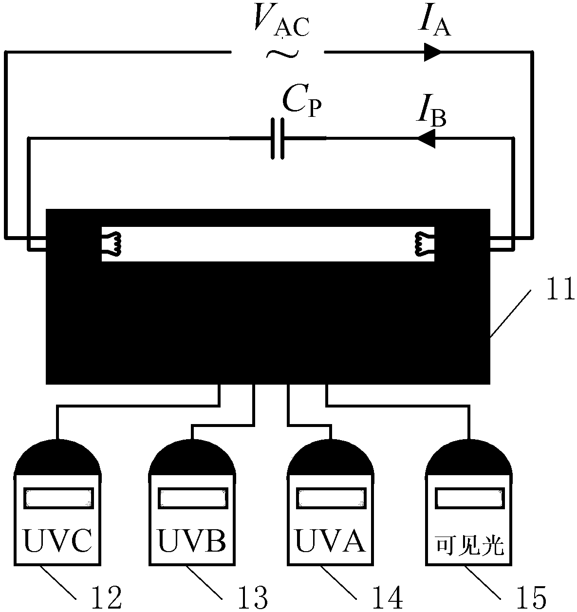
[0060] Specific implementation mode one: see figure 1 and figure 2 Describe this embodiment mode, a kind of electronic ballast experimental platform for driving ultraviolet lamp described in this embodiment mode, it comprises EMI filter 1, full-bridge rectifier 2, power factor correction circuit 3, half-bridge LCC resonant circuit 4 , SCM 5, drive circuit 6, DC filter 7, current acquisition device 8, voltage acquisition device 9, black box 11, UVA measuring instrument 12, UVB measuring instrument 13, UVC measuring instrument 14 and visible light measuring instrument 15;

[0061] After the 220V single-phase alternating current passes through the EMI filter 1 to eliminate electromagnetic interference, it is rectified by the full-bridge rectifier 2 in turn, and the power factor is corrected by the power factor correction circuit 3. After the output bus voltage is tuned by the half-bridge LCC resonant circuit 4, Supply power to the ultraviolet lamp 10; the ultraviolet lamp 10 is...

specific Embodiment approach 2

[0070] Specific implementation mode two: see figure 1 and figure 2 Describe this embodiment, a method for optimizing the driving power of an ultraviolet lamp, which is implemented based on an electronic ballast experimental platform for driving ultraviolet lamps described in the first specific embodiment,

[0071] The method comprises the steps of:

[0072] Step 1: When the single-chip microcomputer 5 receives the voltage at both ends of the ultraviolet lamp 10 collected by the voltage acquisition device 9, it is determined that the ultraviolet lamp 10 is working normally, and at the same time, the single-chip microcomputer 5 determines the input power to the ultraviolet lamp 10 by the current collected by the current acquisition device 8. Value;

[0073] Step 2: adjust the given power received by the ultraviolet lamp 10, so that the power received by the ultraviolet lamp 10 is gradually increased from 60W to 160W, and the increase step is N, where N=5;

[0074] Step 3: Re...

specific Embodiment approach 3

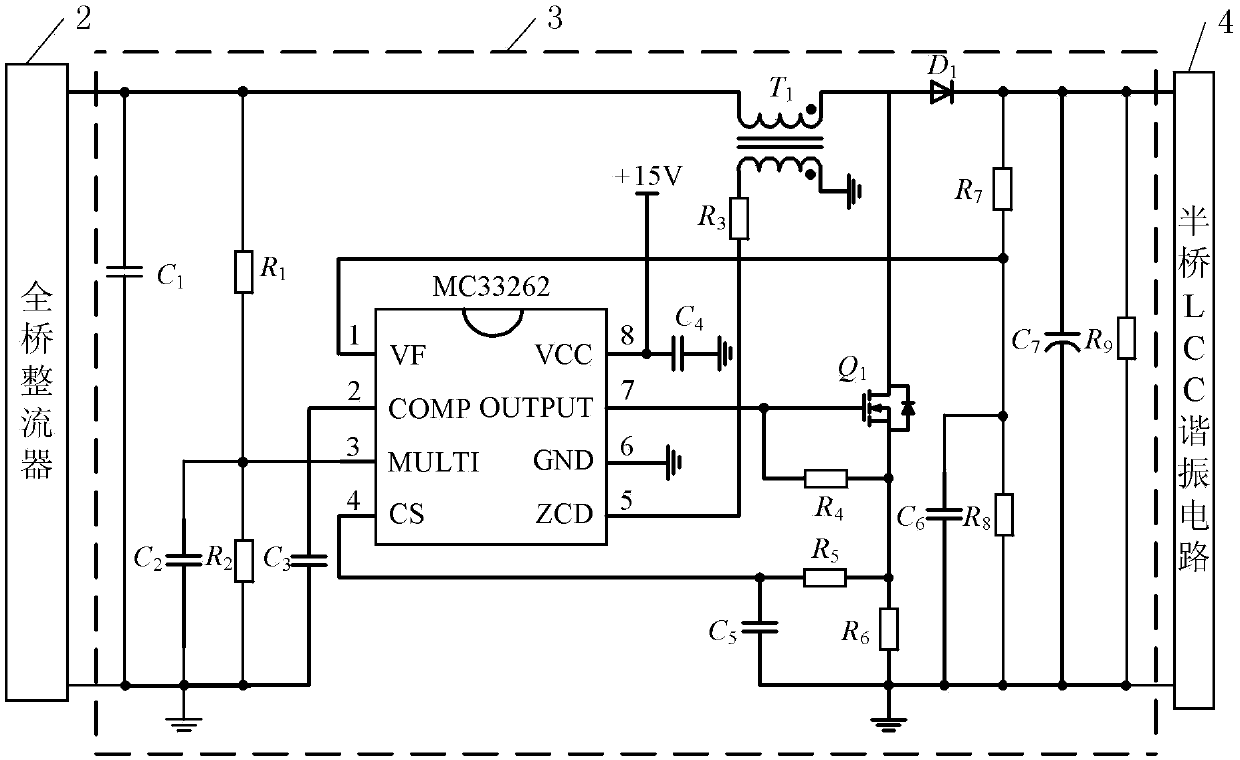
[0086] Specific implementation mode three: see Figure 1 to Figure 3 Describe this embodiment, the difference between this embodiment and the method for optimizing the driving power of an ultraviolet lamp described in the second embodiment is that the power factor correction circuit 3 includes a capacitor C 1 to C 7 , resistance R 1 to R 9 , Diode D 1 , Transformer T 1 , Power switch tube Q 1 And MC33262 chip;

[0087] Capacitance C 1 The two ends of are used as the voltage input terminals of the power factor correction circuit 3;

[0088] Resistance R 9 The two ends of are used as the voltage output terminals of the power factor correction circuit 3;

[0089] Capacitance C 1 One end of the resistor R 1 one end of the transformer T 1 The opposite ends of the primary coil are connected at the same time, the resistance R 1 The other end of the capacitor C 2 One end of the resistor R 2 One end of the chip is connected to pin 3 of the MC33262 chip at the same time; ...


PUM


Abstract

The invention provides an electronic ballast experiment platform for driving an ultraviolet lamp and an optimization method of the driving power of the ultraviolet lamp. The problems of a short service life of the ultraviolet lamp and low short-wave ultraviolet irradiation and low light efficiency caused by a condition that an existing platform for verifying an ultraviolet lamp can not accuratelyset the optimum rated power of the ultraviolet lamp are solved. The electronic ballast experiment platform comprises an EMI filter, a full bridge rectifier, a power factor correction circuit, a half-bridge LCC resonant circuit, a single-chip microcomputer, a driving circuit, a DC filter, a current collection device, a voltage collection device, a black box, a UVA measurement instrument, a UVB measurement instrument, a UVC measurement instrument and a visible light measurement instrument. The platform can be set for the rated power of all lamps, through the platform, the lamp input power is adjusted within a wide range, a variety of test instruments is used to test the irradiation and filament current of each spectrum of the lamp under different power, and thus the irradiation of the lamp under optimum input power is determined. The electronic ballast experiment platform and the optimization method are mainly used for optimizing the rated power of the ultraviolet lamp.

Description

technical field [0001] The invention belongs to the field of ultraviolet lamp driving. Background technique [0002] Ultraviolet lamp manufacturers lack a scientific method to formulate the rated power, and often formulate it according to the method of fluorescent lamps. If the driver or ballast developer drives the ultraviolet lamp according to this power, the irradiance of ultraviolet rays in the required spectrum band may not be enough, or The filament current is too high and the irradiance decays too fast. [0003] The driver or ballast developer is an electrical engineer. If the parameters are designed only according to the rated power, the irradiance of the effective spectrum band will be insufficient, or the attenuation speed will be fast, which will reduce the effective life of the UV lamp. [0004] The short-wave ultraviolet rays produced by ultraviolet lamps have biological inactivation and sterilization effects, and the ultraviolet sewage treatment method will no...

Claims


Application Information

Patent Timeline
Patent Type & Authority Applications(China)
IPC IPC(8): H05B33/08G01J1/00G01J1/42G01R21/00H05B44/00
CPCG01J1/00G01J1/42G01R21/00H05B45/50Y02B20/30
Inventor 张相军徐殿国张芯瑶刘博禹董扣杰王懿杰
Owner HARBIN INST OF TECH
Why Eureka
Try Eureka