An electronic ballast experimental platform for driving ultraviolet lamps and an optimization method for driving power of ultraviolet lamps
A technology for electronic ballasts and ultraviolet lamps, which is used in the measurement of electric power, the use of electric radiation detectors for photometry, and electrical devices, etc. Problems such as low irradiance and luminous efficacy
- Summary
- Abstract
- Description
- Claims
- Application Information
AI Technical Summary
Problems solved by technology
Method used
Image
Examples
specific Embodiment approach 1
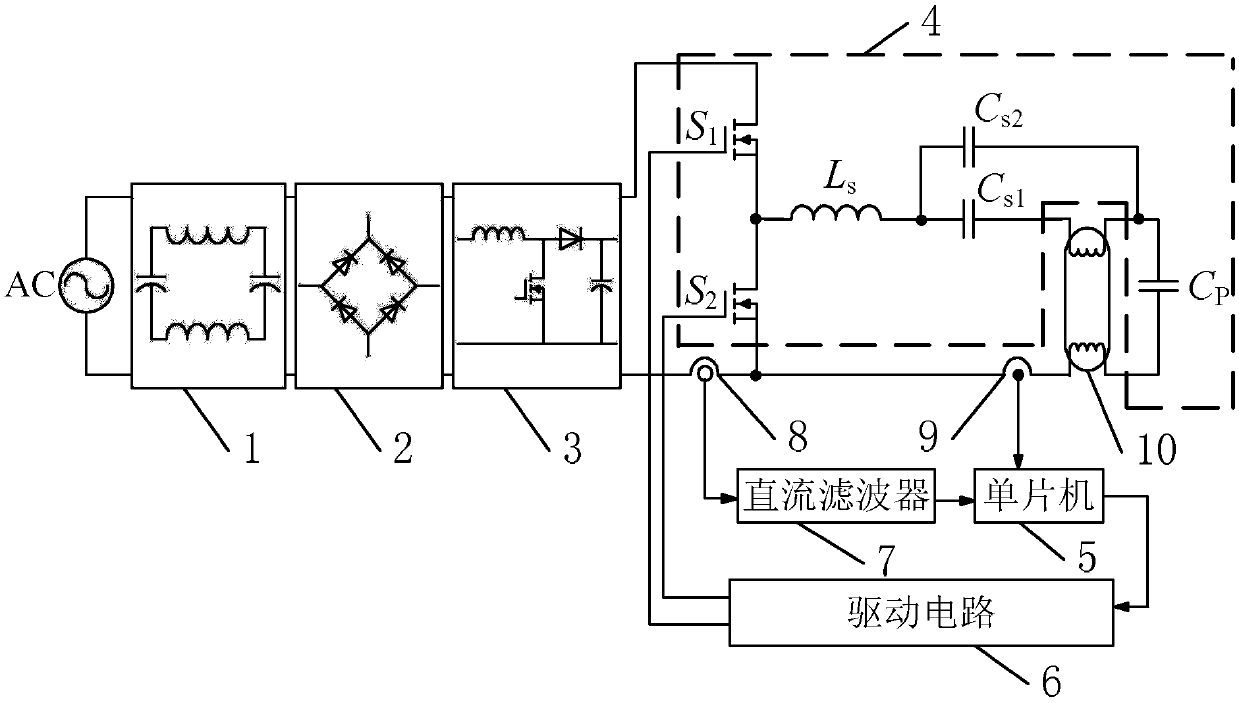
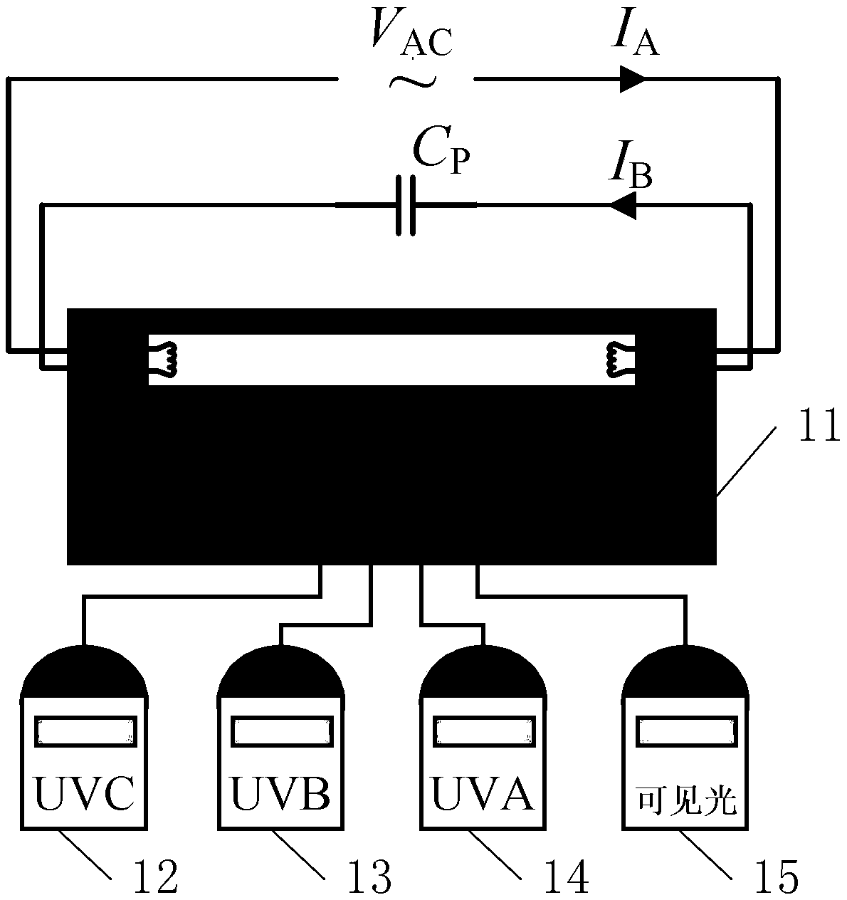
[0060] Specific implementation mode 1: see figure 1 and figure 2 Describe this embodiment, an electronic ballast experimental platform for driving ultraviolet lamps described in this embodiment, which includes an EMI filter 1, a full-bridge rectifier 2, a power factor correction circuit 3, and a half-bridge LCC resonant circuit 4 , SCM 5, drive circuit 6, DC filter 7, current acquisition device 8, voltage acquisition device 9, black box 11, UVA measuring instrument 12, UVB measuring instrument 13, UVC measuring instrument 14 and visible light measuring instrument 15;
[0061] After the 220V single-phase AC power is eliminated by the EMI filter 1, it is rectified by the full-bridge rectifier 2 and the power factor correction by the power factor correction circuit 3. After the output bus voltage is tuned by the half-bridge LCC resonant circuit 4, Supply power to the ultraviolet lamp 10; the ultraviolet lamp 10 is placed in the sealed black box 11, and the probes of the UVA mea...
specific Embodiment approach 2
[0070] Specific implementation two: see figure 1 and figure 2 Describe this embodiment, a method for optimizing the driving power of an ultraviolet lamp, the method is realized based on the experimental platform of an electronic ballast for driving an ultraviolet lamp described in the specific embodiment 1,
[0071] The method includes the following steps:
[0072] Step 1: When the single-chip microcomputer 5 receives the voltage at both ends of the ultraviolet lamp 10 collected by the voltage collecting device 9, it is determined that the ultraviolet lamp 10 is working normally, and the single-chip computer 5 determines the input power to the ultraviolet lamp 10 through the current collected by the current collecting device 8. Value;
[0073] Step 2: Adjust the given power received by the ultraviolet lamp 10, so that the power received by the ultraviolet lamp 10 is gradually increased from 60W to 160W, and the step size of the increase is N, where N=5;
[0074] Step 3: re...
specific Embodiment approach 3
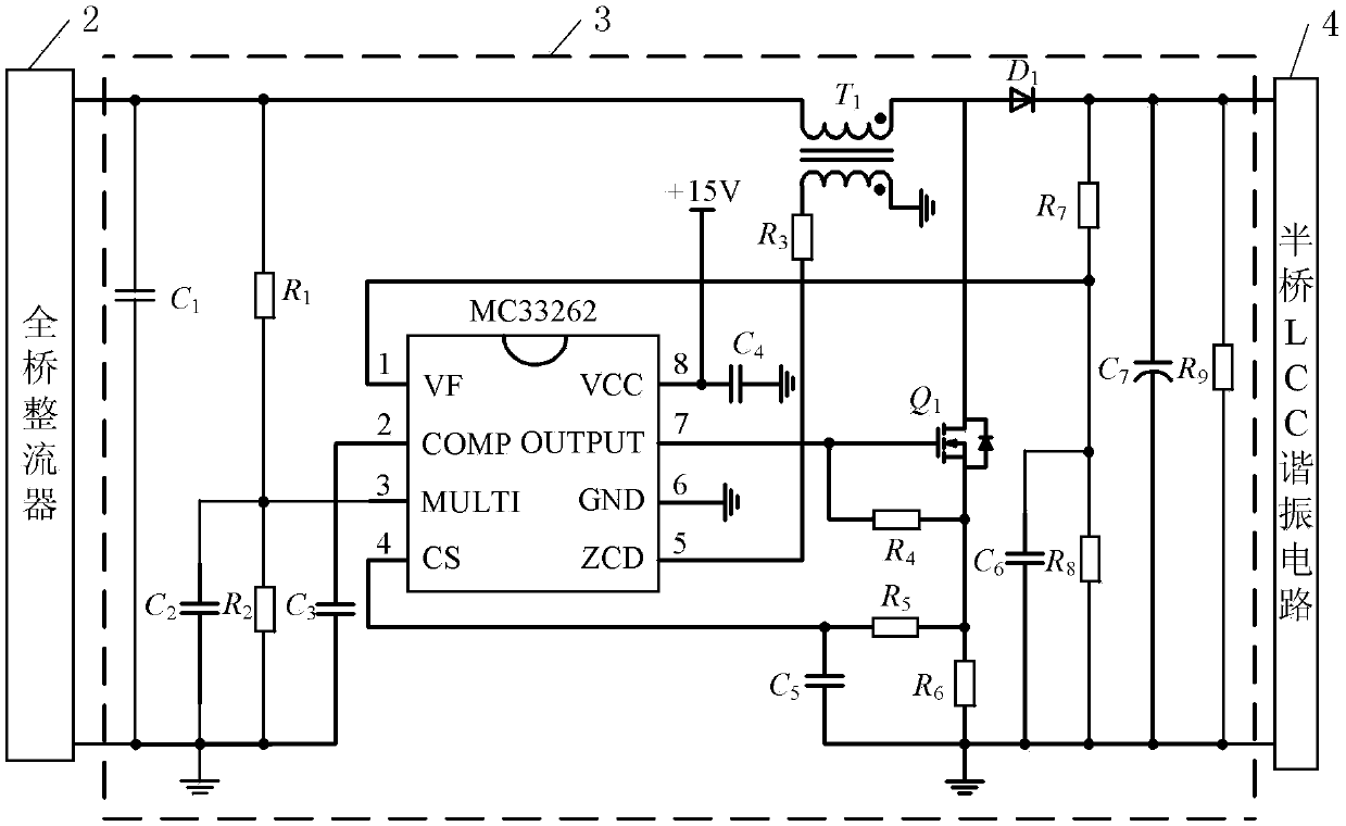
[0086] Specific implementation mode three: see Figure 1 to Figure 3 Describing this embodiment, the difference between this embodiment and the method for optimizing the driving power of an ultraviolet lamp described in Embodiment 2 is that the power factor correction circuit 3 includes a capacitor C 1 to C 7 , resistance R 1 to R 9 , diode D 1 , Transformer T 1 , power switch tube Q 1 and MC33262 chip;
[0087] Capacitor C 1 Both ends of , are used as the voltage input terminals of the power factor correction circuit 3;
[0088] Resistor R 9 The two ends of the power factor correction circuit are used as the voltage output terminal of the power factor correction circuit 3;
[0089] Capacitor C 1 one end with resistor R 1 one end and the transformer T 1 The different ends of the primary coil are connected at the same time, the resistance R 1 The other end of the capacitor C 2 one end of , resistor R 2 One end of MC33262 is connected to pin 3 of the MC33262 chip ...
PUM
 Abstract
Description
Claims
Application Information
 - R&D
- Intellectual Property
- Life Sciences
- Materials
- Tech Scout
- Unparalleled Data Quality
- Higher Quality Content
- 60% Fewer Hallucinations
Browse by: Latest US Patents, China's latest patents, Technical Efficacy Thesaurus, Application Domain, Technology Topic, Popular Technical Reports.
© 2025 PatSnap. All rights reserved.Legal|Privacy policy|Modern Slavery Act Transparency Statement|Sitemap|About US| Contact US: help@patsnap.com


