
Decoring Machine/Vibrating Machine With Improved Drive

A technology of vibrating machine and transmission device, applied in the direction of vibrating fluid, cleaning method and appliance, chemical instrument and method, etc., can solve the problems such as short service life of coring machine/vibrating machine, reduce quality and reduce manufacturing cost , The effect of shortening the drive line

Inactive Publication Date: 2018-02-02
费尔有限公司
View PDF8 Cites 1 Cited by
  • Summary
  • Abstract
  • Description
  • Claims
  • Application Information

AI Technical Summary

Problems solved by technology

[0003] The disadvantage of this arrangement is that the transmission for synchronizing the two unbalanced shafts or eccentric masses is subject to severe vibrations and the corer / vibrator therefore has only a comparatively short service life

Method used


Image

  • Decoring Machine/Vibrating Machine With Improved Drive
  • Decoring Machine/Vibrating Machine With Improved Drive
  • Decoring Machine/Vibrating Machine With Improved Drive

Examples


Embodiment Construction

[0029] First of all, it should be pointed out that in the different described embodiments, the same components are provided with the same reference signs or the same component names, wherein the disclosures contained in the entire specification can be transferred to the same reference signs in a meaningful way. Or on the same part with the same component name. Position descriptions selected in the description, such as upper, lower, lateral, etc., also refer to the directly described and illustrated figures and are transferred by meaning to the new position when a position is changed. Furthermore, individual features or combinations of features in the different exemplary embodiments shown and described can themselves also be independent, inventive or solutions according to the invention.

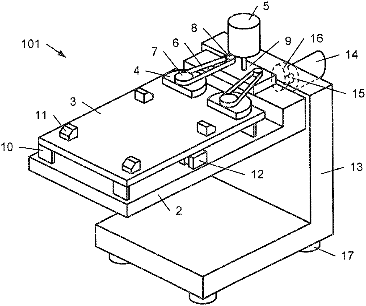
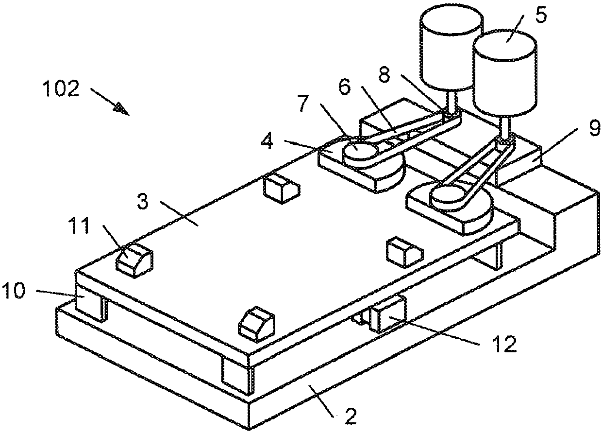
[0030] figure 1 A first example of a corer or vibrator 101 is shown in an oblique view. The corer / vibrator 101 comprises a first frame 2 , a table 3 movably supported relative to the first ...


PUM


Abstract

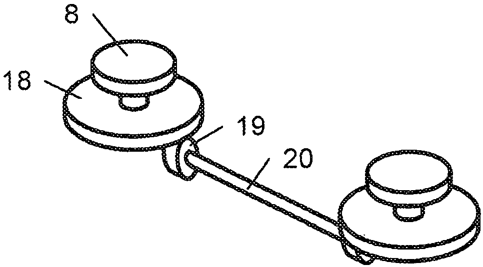
The invention relates to a decoring machine / vibrating machine (101..104), which comprises a first machine frame (2), a machine table (3) mounted such that it can move in relation to the first machineframe (2) for clamping a workpiece, two eccentric masses (4) driven in opposite directions and mounted on the machine table (3), as well as at least one drive motor (5) arranged on the first machine frame (2). A power or torque flow from at least one drive motor (5) to the two eccentric masses (4) is guided such that a branch and / or a junction in the power flow / torque flow or means for synchronizing the two eccentric masses (4) are provided on the first machine frame (2). In addition, the power flow / torque flow between the first machine frame (2) and the machine table (3) is guided via at least one belt (6) leading to each eccentric mass (4).

Description

technical field [0001] The invention relates to a coring machine or a vibrating machine, comprising a first frame, a machine table for clamping workpieces movably and elastically supported relative to the first frame, two counter-driven and an eccentric block supported on the machine table and at least one drive motor arranged on the first frame. Furthermore, the corer / vibrator comprises coupling means for directing a flow of force or torque from the at least one drive motor to the two eccentric masses. Background technique [0002] Coringers / vibrators of the type mentioned are known in principle. For this purpose, AT003791U1 discloses, for example, a device for de-coring a casting body with a sand core, which device comprises a rotor with a horizontal axis of rotation supported in a support, on which the rotor is movable in the direction of the axis of rotation A ground-guided carriage with a receptacle for the cast body and a vibration drive for the carriage. The vibrat...

Claims


Application Information

Patent Timeline
Patent Type & Authority Applications(China)
IPC IPC(8): B22D29/00
CPCB22D29/001B22D29/005B22D29/02B06B1/161B08B7/02
Inventor M·布安德克尔
Owner 费尔有限公司
Learn More