Showing stand for pipe fitting selling

A technology for display racks and pipe fittings, which is applied in applications, display hangers, display shelves, etc. It can solve the problems that pipe fittings cannot be displayed at multiple angles, inconvenient pipe fittings display, etc., and achieve good stability, avoid shaking, and improve practicality.

Inactive Publication Date: 2018-02-06
翟听志
0 Cites 19 Cited by

AI-Extracted Technical Summary

Problems solved by technology

[0004] The purpose of the present invention is to provide a display stand for pipe fittings sales, which has the advantage that the display board can be rotated, and solves the...

Method used

Please refer to Fig. 1-4, a kind of display stand for pipe fitting sales, comprising housing 1, the bottom of housing 1 is symmetrically fixedly connected with wheel 25, and the inner cavity of wheel 25 is movably connected with wheel frame 26 through the second rotating shaft , through the setting of the first rotating shaft, it plays the role of articulated roller 24, through the cooperative use of the wheel 25 and the wheel frame 26, the user can easily move the display stand, thus achieving the ease of movement of the display stand As a result, the top of the housing 1 is provided with a rotating column 2, and the surface of the rotating column 2 is sequentially provided with a first display board 3 and a second display board 4 from bottom to top. The top of the housing 1 is provided with a chute 22, and the chute 22 is circular in shape, and the bottom of the first display board 3 is symmetrically fixedly connected with a roller frame 23, and the inner cha...

Abstract

The invention discloses a display stand for selling pipe fittings, which comprises a casing, a rotating column is arranged on the top of the casing, and a first display board and a second display board are sequentially sleeved on the surface of the rotating column from bottom to top, The top of the rotating column is fixedly connected with a top plate, the top of the first display board is fixedly connected with a first anti-slip pad, and the top of the second display board is fixedly connected with a second anti-slip pad. The present invention uses rotating column, turntable, first fixed block, fixed column, second fixed block, motor, first bevel gear, second bevel gear, rotating shaft, movable block, third fixed block, movable plate, opening Cooperating with the card slot, it solves the problem that the existing pipe fitting display rack cannot display the pipe fittings from multiple angles when selling the pipe fittings, and it is inconvenient to display the pipe fittings. The display rack for pipe fitting sales has the advantage that the display board can be rotated , which is beneficial to the sales of pipe fittings and improves the practicability of the pipe fitting display stand.

Application Domain

Technology Topic

EngineeringDisplay board +2

Image

  • Showing stand for pipe fitting selling
  • Showing stand for pipe fitting selling
  • Showing stand for pipe fitting selling

Examples

  • Experimental program(1)

Example Embodiment

[0019] The technical solutions in the embodiments of the present invention will be clearly and completely described below in conjunction with the accompanying drawings in the embodiments of the present invention. Obviously, the described embodiments are only a part of the embodiments of the present invention, rather than all the embodiments. Based on the embodiments of the present invention, all other embodiments obtained by those of ordinary skill in the art without creative work shall fall within the protection scope of the present invention.
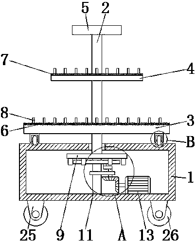
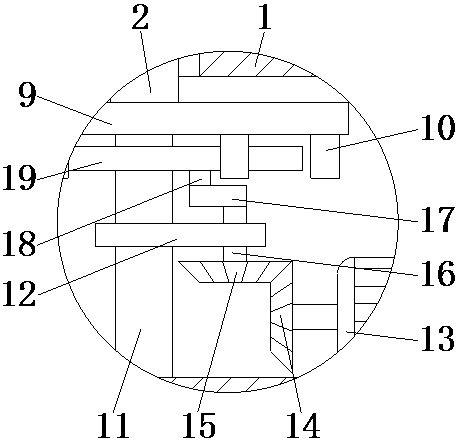
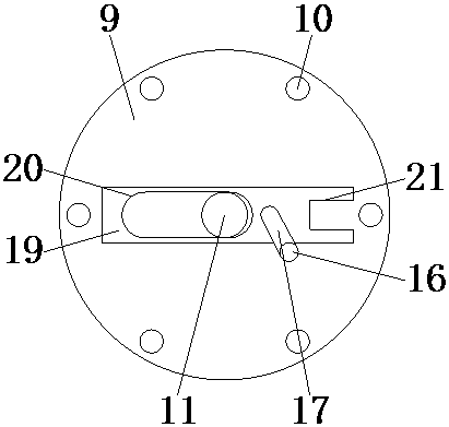
[0020] See Figure 1-4 , A display rack for pipe fittings sales, comprising a housing 1, the bottom of the housing 1 is symmetrically fixedly connected with wheels 25, the inner cavity of the wheel 25 is movably connected with a wheel frame 26 through a second rotating shaft, through the setting of the first rotating shaft, With the function of the movable connection roller 24, the user can easily move the display rack through the cooperative use of the wheels 25 and the wheel frame 26, thereby achieving the effect of facilitating the movement of the display rack. The top of the housing 1 is provided with Rotating column 2, the surface of the rotating column 2 is sequentially sleeved with a first display board 3 and a second display board 4 from bottom to top. The top of the housing 1 is provided with a sliding groove 22, which is circular in shape. The bottom of a display board 3 is symmetrically fixedly connected with a roller frame 23. The inner cavity of the roller frame 23 is movably connected with the roller 24 through the first rotating shaft. The second rotating shaft is arranged to play the role of movably connecting the wheel frame 26. 22. The combined use of the roller rack 23 and the roller 24 supports the first display board 3, and at the same time prevents the first display board 3 from shaking when rotating, and increases the rotation of the first display board 3 The stability of the first display board 3 makes the first display board 3 more stable. The top of the rotating column 2 is fixedly connected to the top board 5, and the top of the first display board 3 is fixedly connected to the first anti-skid pad 6, and the second display board 4 A second anti-skid pad 7 is fixedly connected to the top, and a fixing rod 8 is fixedly connected to the tops of the first anti-skid pad 6 and the second anti-skid pad 7;
[0021] The bottom of the rotating column 2 penetrates into the inner cavity of the housing 1 and is fixedly connected with a turntable 9. The top of the housing 1 is provided with a through hole adapted to the rotating column 2, and the bottom of the turntable 9 is fixedly connected with a first fixing block 10 , The number of the first fixed blocks 10 is six, and the six first fixed blocks 10 are evenly distributed. The central axis at the bottom of the turntable 9 is movably connected with a fixed column 11, and the bottom of the fixed column 11 is in the housing 1. The bottom of the cavity is fixedly connected, the surface of the fixed column 11 is fixedly connected with a second fixed block 12, the right side of the bottom of the inner cavity of the fixed column 11 is fixedly connected with a motor 13, and the output shaft of the motor 13 is fixedly connected with a first bevel gear 14. The top of the first bevel gear 14 is meshed with a second bevel gear 15, the surface of the first bevel gear 14 is provided with first teeth, and the surface of the second bevel gear 15 is provided with the first teeth to match The top of the second bevel gear 15 is fixedly connected with a rotating shaft 16, the top of the rotating shaft 16 penetrates to the top of the second fixed block 12 and is fixedly connected with a movable block 17, the surface of the rotating shaft 16 passes through a bearing It is movably connected to the inner wall of the second fixed block 12, the left side of the top of the movable block 17 is fixedly connected with a third fixed block 18, the surface of the fixed column 11 on the top of the second fixed block 12 is covered with a movable plate 19, and the third fixed block The top of 18 is movably connected with the bottom of the movable plate 19, the bottom of the movable plate 19 is provided with an opening 20 adapted to the fixed column 11, and the right side of the movable plate 19 is provided with a card slot 21 for use with the first fixed block 10 .
[0022] In use, the user turns on the motor 13, the motor 13 drives the first bevel gear 14 to rotate, the first bevel gear 14 drives the second bevel gear 15 to rotate, and the second bevel gear 15 drives the rotation shaft 16 to rotate. 16 drives the movable block 17 to rotate, the movable block 17 drives the third fixed block 18 to rotate, the third fixed block 18 drives the movable plate 19 to rotate, and the movable plate 19 drives the clamping slot 21 so that the first fixed block 10 is clamped into the clamping slot 21 to move The rotation of the plate 19 drives the first fixed block 10 to rotate, the first fixed block 10 drives the turntable 9 to rotate, the turntable 9 drives the rotating column 2 to rotate, the rotating column 2 drives the first display board 3 and the second display board 4 to rotate, and then the movable block The rotation of 17 drives the slot 21 to be separated from the first fixing block 10, and then the next first fixing block 10 is clamped into the slot 21. This cycle of operation can achieve the effect of multi-angle display of the pipe fitting sales display rack .
[0023] In summary: the display rack for pipe fittings sales passes through the rotating column 2, the turntable 9, the first fixed block 10, the fixed column 11, the second fixed block 12, the motor 13, the first bevel gear 14, the second cone The coordinated use of gear 15, rotating shaft 16, movable block 17, third fixed block 18, movable plate 19, opening 20, and card slot 21 solves the problem that the existing pipe fitting display rack cannot carry out multiple pipe fittings when selling pipe fittings. Angle display, inconvenient for the display of pipe fittings.
[0024] Although the embodiments of the present invention have been shown and described, those of ordinary skill in the art can understand that various changes, modifications, and substitutions can be made to these embodiments without departing from the principle and spirit of the present invention. And variations, the scope of the present invention is defined by the appended claims and their equivalents.

PUM

no PUM

Description & Claims & Application Information

We can also present the details of the Description, Claims and Application information to help users get a comprehensive understanding of the technical details of the patent, such as background art, summary of invention, brief description of drawings, description of embodiments, and other original content. On the other hand, users can also determine the specific scope of protection of the technology through the list of claims; as well as understand the changes in the life cycle of the technology with the presentation of the patent timeline. Login to view more.

Similar technology patents

Optical device

Owner:SUMITOMO ELECTRIC IND LTD

Classification and recommendation of technical efficacy words

  • Avoid shaking
  • Improve practicality
Why Eureka
Try Eureka