Control method, device and system of oven fan and oven

An oven and fan technology, applied in pump control, engine control, roaster/barbecue grid, etc., can solve problems such as long opening and closing cycles, inability to accurately control the internal temperature of the oven, and large fluctuations in the internal temperature of the oven. The effect of stable temperature and reduced fluctuation

Active Publication Date: 2018-02-06
GREE ELECTRIC APPLIANCES INC
View PDF7 Cites 9 Cited by
  • Summary
  • Abstract
  • Description
  • Claims
  • Application Information

AI Technical Summary

Problems solved by technology

[0005] Embodiments of the present invention provide a control method, device, system, and oven for an oven fan, to at least solve the problem in the prior art that the internal temperature of the oven fluctuates greatly within one cycle due to the long relay opening and closing cycle of the oven, which cannot The technical problem of precise control of the internal temperature of the oven

Method used


Image

  • Control method, device and system of oven fan and oven
  • Control method, device and system of oven fan and oven
  • Control method, device and system of oven fan and oven

Examples


Embodiment 1

[0020] According to an embodiment of the present invention, a method embodiment of a method for controlling an oven fan is provided. It should be noted that the steps shown in the flow chart of the accompanying drawings can be executed in a computer system such as a set of computer-executable instructions, Also, although a logical order is shown in the flowcharts, in some cases the steps shown or described may be performed in an order different from that shown or described herein.

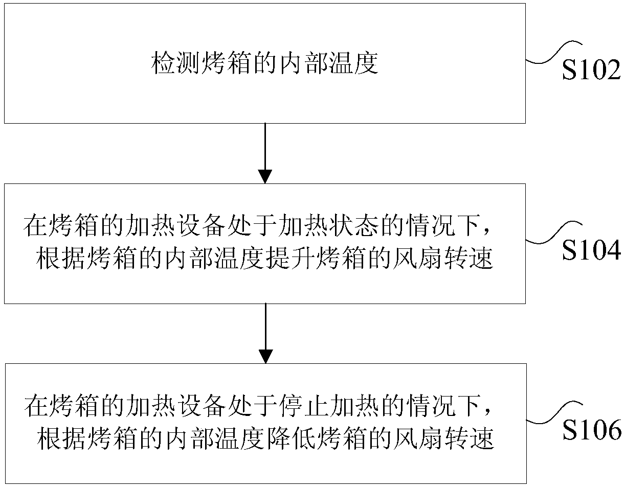
[0021] figure 1 is a flow chart of a method for controlling an oven fan according to an embodiment of the present invention, such as figure 1 As shown, the method includes the following steps:

[0022] Step S102, detecting the internal temperature of the oven.

[0023] Step S104, when the heating device of the oven is in a heating state, increase the fan speed of the oven according to the internal temperature of the oven.

[0024] Step S106 , when the heating device of the oven is in a state of ...

Embodiment 2

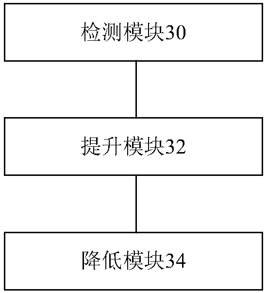
[0088] image 3 It is a structural schematic diagram of a control device for an oven fan according to an embodiment of the present invention. The architecture depicted is only one example of a suitable environment for descriptive purposes and is not intended to suggest any limitation as to the scope of use or functionality of the application. Nor should an oven fan control be considered a image 3 Any component or combination shown has any dependencies or requirements, the installation including:

[0089] The detection module 30 is used for detecting the internal temperature of the oven.

[0090] The raising module 32 is used for raising the fan speed of the oven according to the internal temperature of the oven when the heating equipment of the oven is in a heating state.

[0091] The lowering module 34 is configured to reduce the fan speed of the oven according to the internal temperature of the oven when the heating equipment of the oven is in a state of stopping heating...

Embodiment 3

[0116] According to an embodiment of the present invention, there is also provided a control system for an oven fan for implementing the above oven fan control method, such as Figure 4 As shown, the system includes

[0117] The temperature sensor 40 is used to detect the internal temperature of the oven.

[0118] The controller 42 is connected with the temperature sensor 40, and is used to increase the fan speed of the oven according to the internal temperature of the oven when the heating equipment of the oven is in a heating state; The internal temperature reduces the oven fan speed.

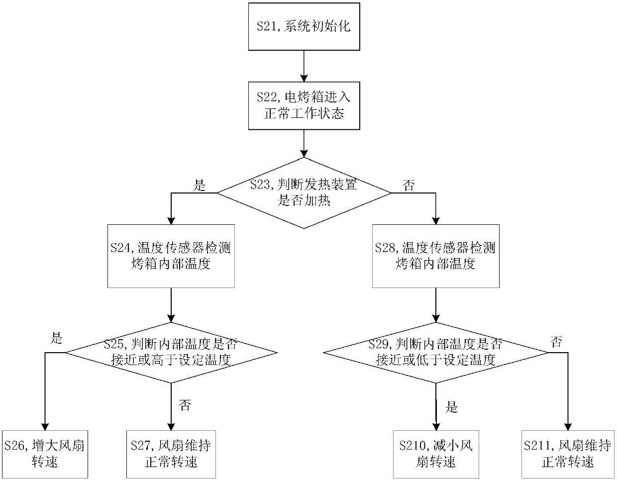
[0119] In an optional embodiment, when adjusting the fan speed of the oven according to the internal temperature of the oven, it can also be adjusted in conjunction with the working state of the heating equipment of the oven. For example, when the heating equipment of the oven is in a heating state, the temperature sensor can Detect the internal temperature of the oven. When the internal te...


PUM


Abstract

The invention discloses a control method, device and system of an oven fan and an oven, wherein the method comprises the following steps of detecting an internal temperature of the oven; under the condition that heating equipment of the oven is in a heating state, increasing the rotational speed of the fan of the oven according to the internal temperature of the oven; and under the condition thatthe heating equipment of the oven is in a state of stopping heating, reducing the rotational speed of the fan of the oven according to the internal temperature of the oven. The control method, deviceand system of the oven fan and the oven solve the technical problem that as the opening period of a relay of the oven is longer, the fluctuation of the internal temperature of the oven in one period is lager, and the internal temperature of the oven cannot be accurately controlled in the prior art.

Description

technical field [0001] The invention relates to the field of electrical appliances, in particular to a control method, device, system and oven for an oven fan. Background technique [0002] At present, most electric ovens usually use a relay to control the start and stop of the heating device, so as to heat the food. The basic control principle of such an oven is: the internal temperature of the oven is detected by the temperature sensing device, and the collected temperature signal is transmitted to the single-chip microcomputer. In the working state, the internal temperature of the oven is controlled within a certain range by means of intermittent heating. [0003] However, since the switching frequency of the relay itself is low, and the working life is limited by the number of switching times, the switching cycle of the relay is relatively long in practical applications. In a working cycle, when the relay is closed, the heating device starts to work, and the temperatur...

Claims


Application Information

Patent Timeline
Patent Type & Authority Applications(China)
IPC IPC(8): F04D27/00A47J37/06A21B1/40
CPCA21B1/40A47J37/0629F04D27/004F05D2270/303
Inventor 白龙张荣
Owner GREE ELECTRIC APPLIANCES INC
Why Eureka
Try Eureka