

A digital logic circuit module with reset deburring function
A digital logic circuit and deburring technology, which is applied in the field of integrated circuits, can solve problems such as difficult to simultaneously remove positive edge burrs, clock/reset function deadlock, and limited burr length
- Summary
- Abstract
- Description
- Claims
- Application Information
AI Technical Summary
Problems solved by technology
Method used
Image

Examples
Embodiment Construction
[0036] Attached below Figure 2-Figure 8 , the specific embodiment of the present invention will be further described in detail.
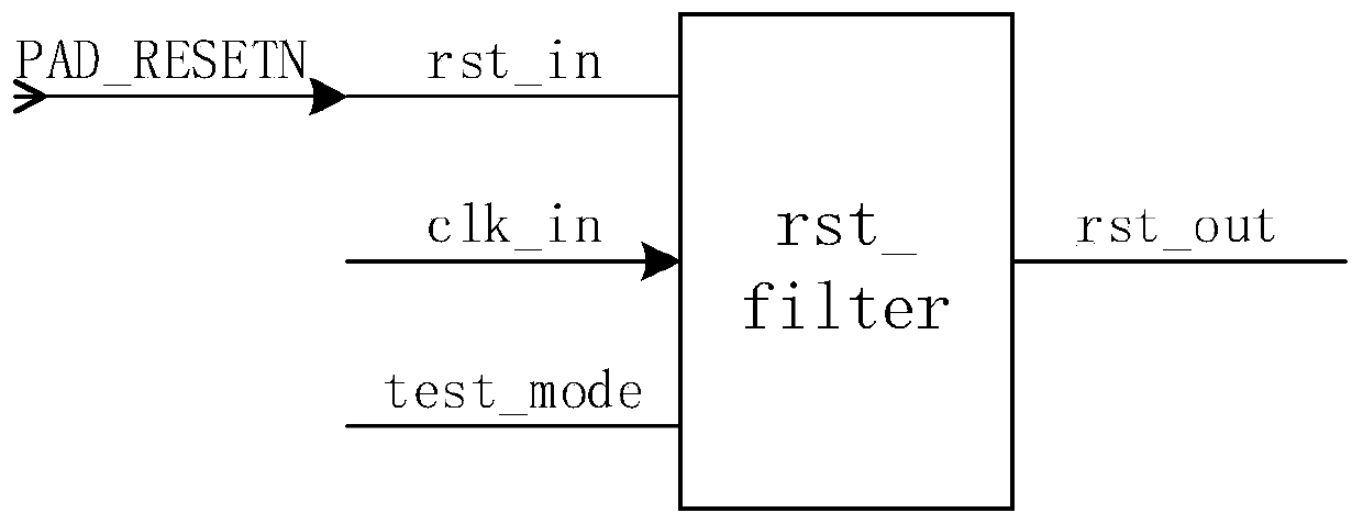
[0037] see figure 2 , figure 2 Shown is a schematic structural diagram of a digital logic circuit module with a reset and deburring function of the present invention. Such as figure 2 As shown, the digital logic circuit module rst_filter includes an input terminal rst_in, an output terminal rst_out, an input terminal of a test mode control signal test_mode, and an input terminal of a synchronous clock signal clk_in. The digital logic circuit module with reset and deburring function of the present invention uses the specific circuit design so that the internal D flip-flop is driven by the synchronous clock signal clk_in after the input clock is stabilized for a period of time after power-on. In the following, the digital logic circuit module rst_filter is divided into four functional modules (negative edge glitch removal unit, positive edge g...
PUM
 Abstract
Description
Claims
Application Information