
Three-phase tissue engineering scaffold

A tissue engineering scaffold, a three-phase technology, applied in tissue regeneration, prosthesis, medical science, etc., can solve the problems of lack of gradient structure regeneration, easy re-fracture of bone and tendon structure, and inability to disperse stress and avulsion of bone and tendon junctions. , to achieve the effect of promoting regeneration and healing, reducing the time of decellularization, and accelerating the process of decellularization

Active Publication Date: 2018-02-09
XIANGYA HOSPITAL CENT SOUTH UNIV
View PDF9 Cites 11 Cited by
  • Summary
  • Abstract
  • Description
  • Claims
  • Application Information

AI Technical Summary

Problems solved by technology

[0003] The traditional method of treating bone-tendon junction injuries often uses various surgical suture techniques to directly fix the tendon or ligament to the bone. The bone-tendon junction is filled with fibrous scar tissue in the early stage, and the reconstruction of its characteristic fibrocartilage layer is incomplete. The regeneration of the gradient structure, so it cannot effectively disperse the stress and prevent the avulsion of the bone-tendon junction, and the reconstructed bone-tendon structure is prone to rupture again after returning to sports
In recent years, with the improvement of surgical methods and the development of postoperative rehabilitation measures, great progress has been made in the healing of bone-tendon junctions, but the injured bone-tendon junctions still cannot fully restore to the normal tissue gradient structure, and their healing The effect is unsatisfactory

Method used


Image

  • Three-phase tissue engineering scaffold
  • Three-phase tissue engineering scaffold
  • Three-phase tissue engineering scaffold

Examples


Embodiment Construction

[0021] The present invention will be further described in detail below in conjunction with the accompanying drawings and specific embodiments.

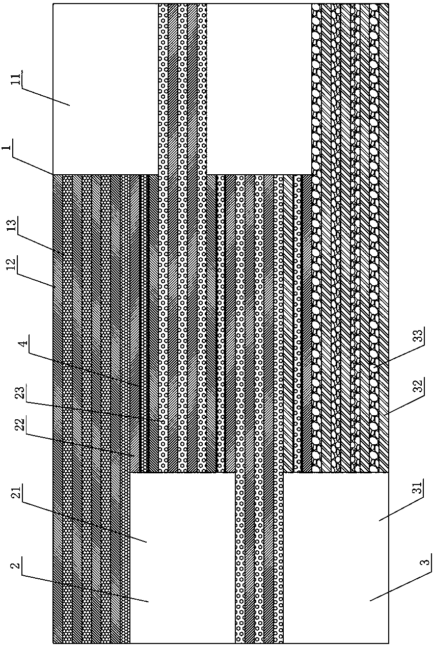
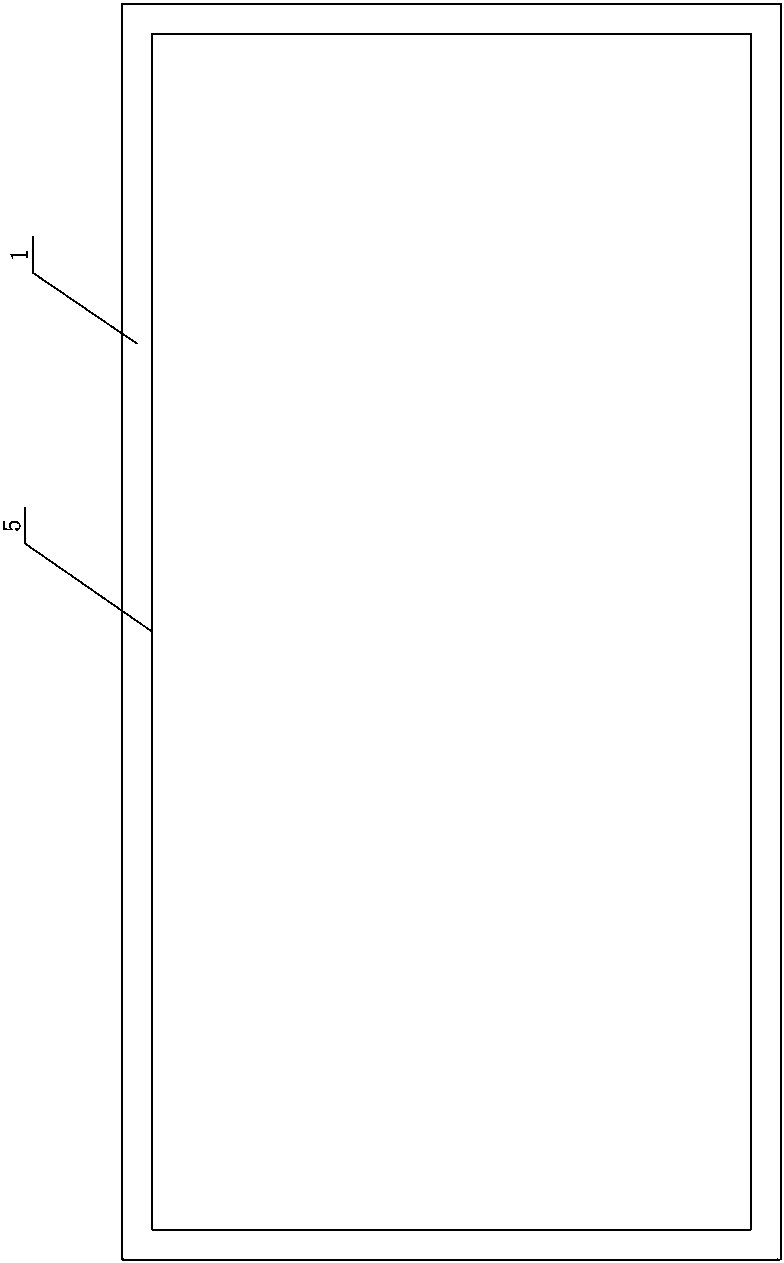
[0022] Such as Figure 1 to Figure 3 As shown, an embodiment of the three-phase tissue engineering scaffold of the present invention includes a bone scaffold 1, a cartilage scaffold 2 and a tendon scaffold 3 stacked and integrated sequentially from top to bottom, and one end of the bone scaffold 1 is set as a bone fixation cladding part 11. The other end of the bone bracket 1 is cut transversely and provided with a plurality of bone leaf sheets 12 extending to the bone fixation wrapping part 11, and a bone differentiation cell sheet 13 is arranged between each bone leaf sheet 12; one end of the cartilage bracket 2 Set as the cartilage-fixed wrapping portion 21, the other end of the cartilage support 2 is cut transversely and provided with a plurality of cartilage-like leaf sheets 22 extending to the cartilage-fixed wrapping portion 21...


PUM


Abstract

The invention discloses a three-phase tissue engineering scaffold, which comprises a bone scaffold, a cartilage scaffold and a tendon scaffold, wherein a bone fixing wrapping page part is arranged atone end of the bone scaffold; bone page sheets are arranged at the other end of the bone scaffold in a tangent mode; bone differentiation cell sheets are arranged between the various bone page sheets;a cartilage fixing wrapping page part is arranged at one end of the cartilage scaffold; cartilage page sheets are arranged at the other end of the cartilage scaffold in a tangent mode; cartilage differentiation cell sheets are arranged between the various cartilage page sheets; a tendon fixing wrapping page part is arranged at one end of the tendon scaffold; tendon page sheets are arranged at theother end of the tendon scaffold in a tangent mode; tendon differentiation cell sheets are arranged between the various tendon page sheets; the bone page sheet at the lowest part of the bone scaffoldis connected to the cartilage page sheet at the topmost side of the cartilage scaffold; and the cartilage page sheet at the lowest part of the cartilage scaffold is connected to the tendon page sheetat the topmost side of the tendon scaffold. The tissue engineering scaffold has the advantages of being simple to prepare, convenient to uses and capable of shortening a cell removal time and improving repair quality.

Description

technical field [0001] The invention mainly relates to the defect repair technology of the joint of bone and tendon, in particular to a three-phase tissue engineering support. Background technique [0002] Bone tendon junction injury (such as patella-patella tendon injury) is a common motor system disease, its incidence is increasing year by year, and its treatment has brought a heavy economic burden to society and families. A typical bone-tendon junction consists of four layers: bone, mineralized fibrocartilage, unmineralized fibrocartilage, and tendon. Different from the repair after injury between the same tissue (such as bone-bone, tendon-tendon), the repair of bone and tendon injury occurs between two tissues with completely different structures, bone and tendon, and the bone and tendon injury is often accompanied by a fibrocartilage layer The damage of bone and tendon injury, the poor blood supply and weak regeneration ability of this part make the repair of bone and ...

Claims


Application Information

Patent Timeline
Patent Type & Authority Applications(China)
IPC IPC(8): A61F2/00A61L27/38A61L27/34A61L27/36
CPCA61F2/0059A61F2/0077A61F2002/0086A61L27/34A61L27/3604A61L27/3608A61L27/3612A61L27/365A61L27/3654A61L27/3662A61L27/3834A61L27/3847A61L27/3852A61L27/386A61L2400/18A61L2430/02A61L2430/06A61L2430/10
Inventor 吕红斌瞿瑾胡建中周永春
Owner XIANGYA HOSPITAL CENT SOUTH UNIV
Learn More