

Automatic sorting and boxing equipment of component assembly line based on vision
A technology for automatic sorting and parts, applied in sorting and other directions, can solve the problem that products cannot be automatically sorted and packaged according to the model, and achieve the effect of fast calculation speed, meeting factory needs, and high calculation accuracy
- Summary
- Abstract
- Description
- Claims
- Application Information
AI Technical Summary
Problems solved by technology
Method used
Image

Examples
Embodiment Construction
[0019] The present invention will be further described below in conjunction with the accompanying drawings and embodiments.
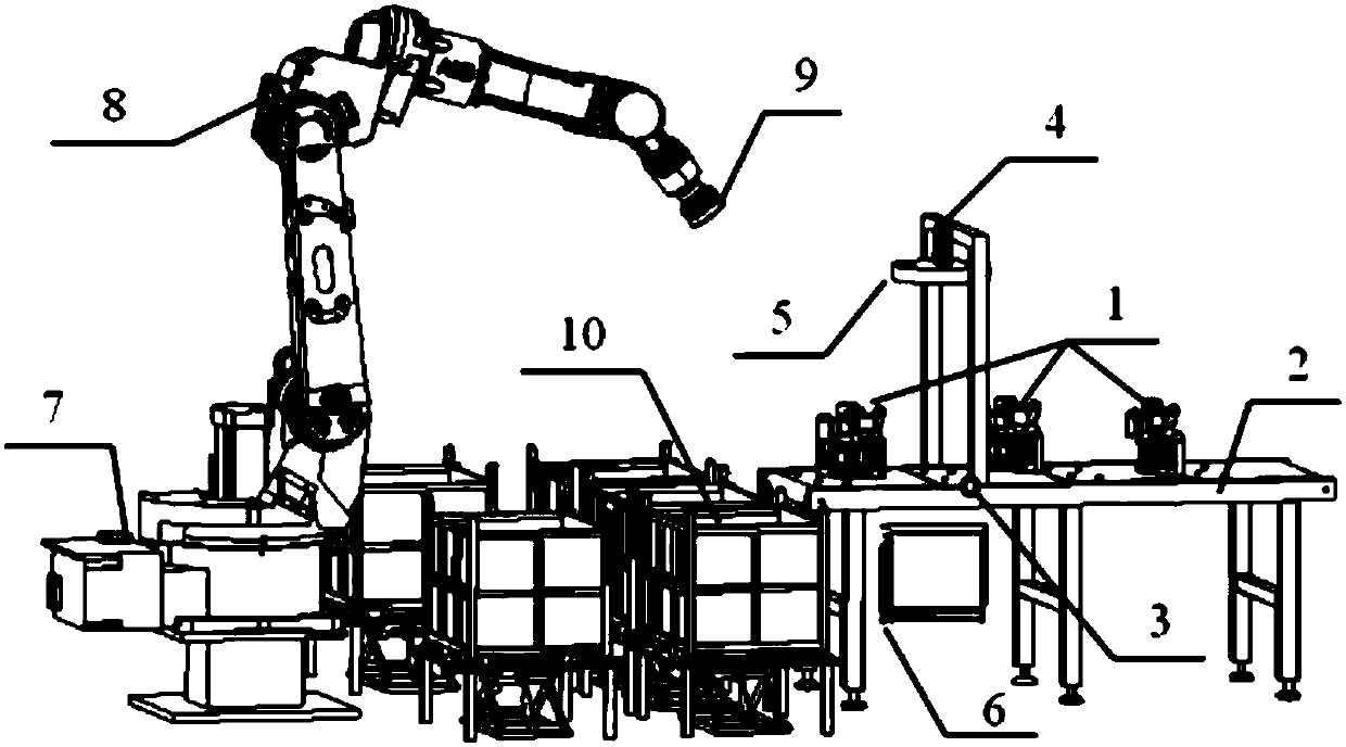
[0020] This embodiment discloses a vision-based automatic sorting and packing device for parts assembly line, which is a non-contact image processing method based on vision, such as figure 1 As shown, it includes parts 1 randomly placed on the conveyor belt 2, conveyor belt 2, proximity switch 3, area array camera 4, ring LED light source 5, industrial computer for image processing 6, robot controller 7, six-axis A mechanical arm 8, a suction cup 9 and a material box 10 for packaging different types, an area array camera 4 and an LED light source 5 are installed above the conveyor belt 2, and the proximity switch 3 is located within the field of view of the camera.
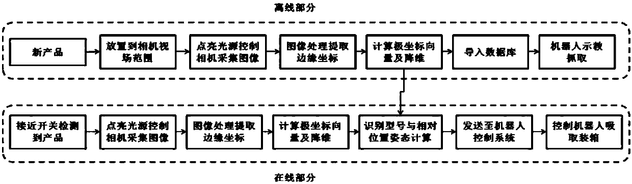
[0021] like figure 2 As shown, the specific operation process is as follows: first, when the conveyor belt 2 adds a new type of component 1, it is necessary to place the component 1 offli...
PUM
 Abstract
Description
Claims
Application Information