Intelligent continuous assembly blanking device

A blanking device and intelligent technology, applied in metal processing, metal processing equipment, manufacturing tools, etc., can solve problems such as work-related injuries, large assembly energy consumption, and operator hand injuries.

Active Publication Date: 2018-02-09
浙江坤邦机械有限公司
View PDF6 Cites 10 Cited by
  • Summary
  • Abstract
  • Description
  • Claims
  • Application Information

AI Technical Summary

Problems solved by technology

For example, for the connection between the rotating shaft 01 and the disc 02, the disc 02 is provided with a mounting hole 03 for the insertion of the rotating shaft 01. The traditional assembly is to manually install one by one. The rotating shaft 01 is plugged into the disc 02, so as to realize the interference fit between the rotating shaft 01 and the mounting hole 03 on the disc 02; in the prior art, there are also automatic assembly through mechanical devices, mainly through the automatic press-fitting of the punching machine, but When the disc 02 and the rotating shaft 01 are successively placed under the punch of the punching machine, work-related injuries are likely to occur, that is, the punch of the punching machine is likely to come into contact with the operator's hand and cause the operator's hand to be injured; and, this punching form The assembly consumes a lot of energy and the level of automation is low

Method used


Image

  • Intelligent continuous assembly blanking device
  • Intelligent continuous assembly blanking device
  • Intelligent continuous assembly blanking device

Examples


Embodiment Construction

[0031] The present invention will be further described below with reference to the drawings and specific embodiments.

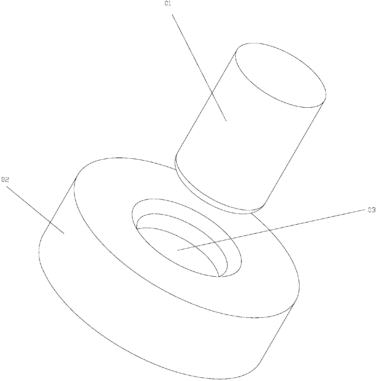
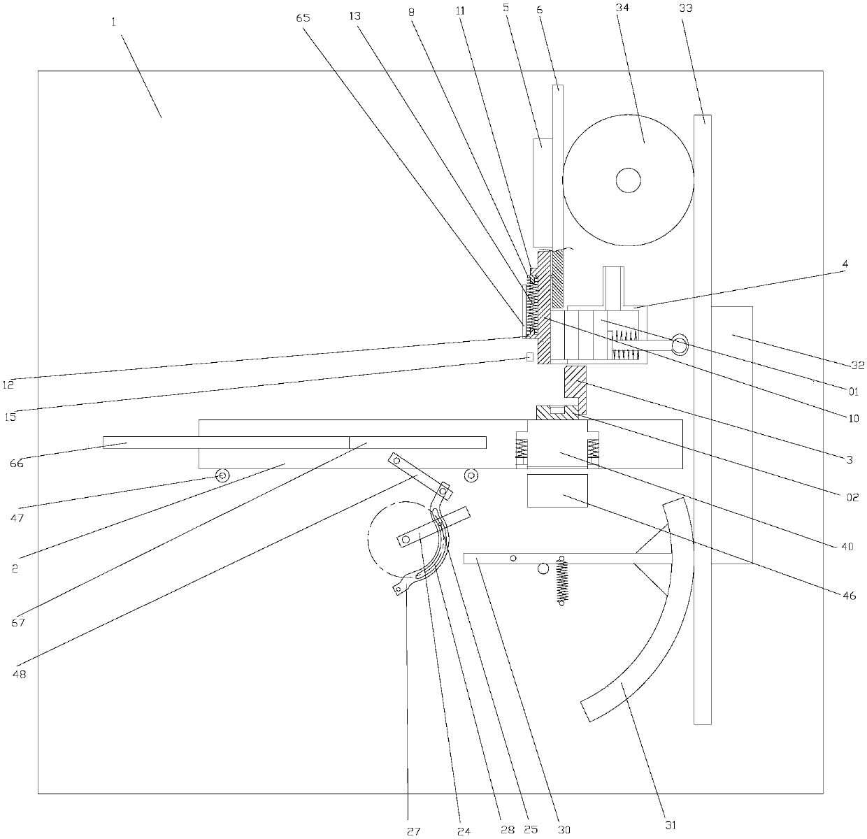
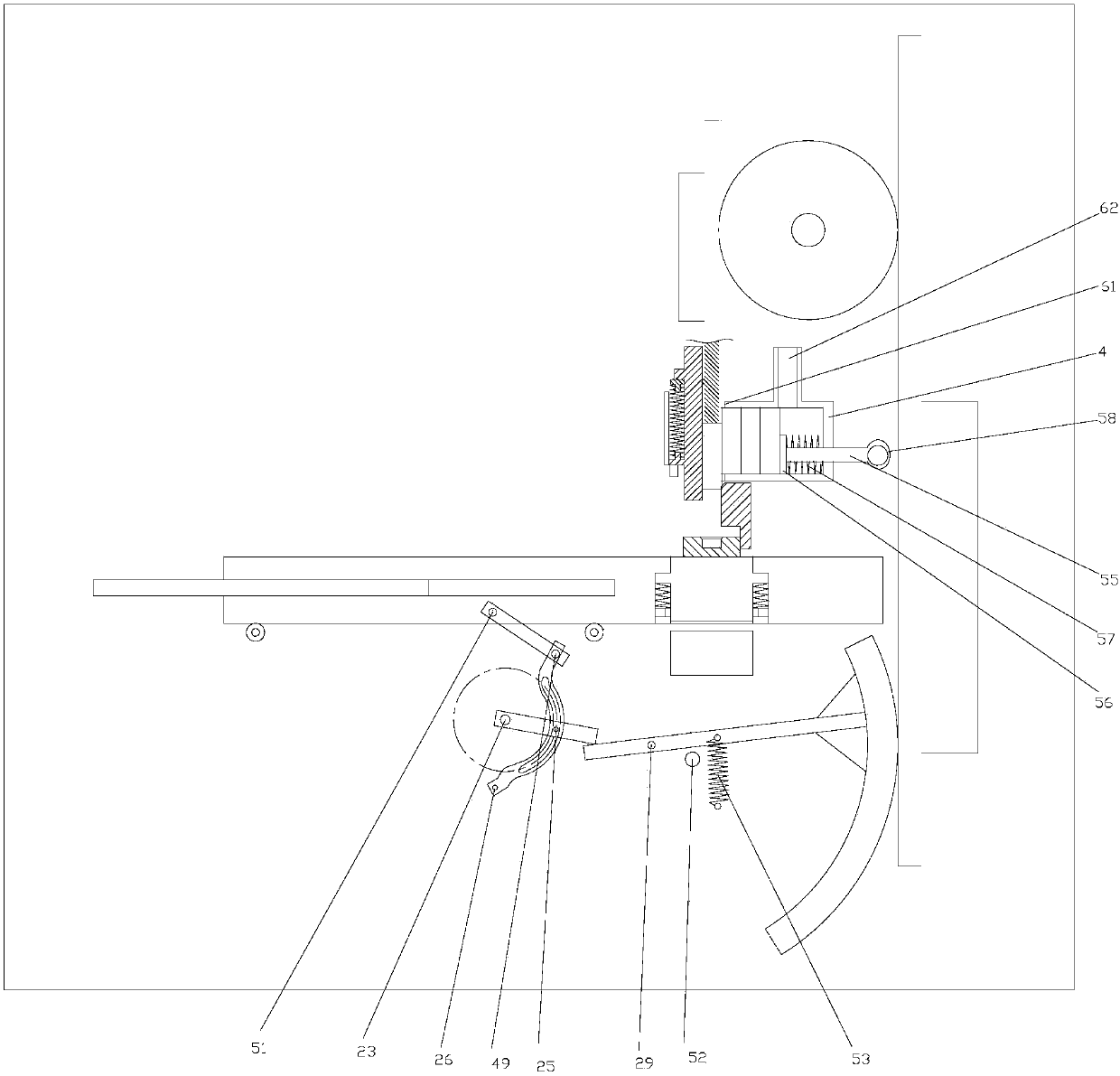
[0032] As shown in the figure, the intelligent continuous assembling blanking device of the present invention includes a base 1, on which a sliding table 2 for placing a disc 02 is slidably connected; The disc 02 is a stopper 3, and the base 1 is provided with a barrel 4 for accommodating the rotating shaft 01 above the stopper 3. The rotating shaft 01 is arranged in the barrel 4 in a vertical state; the base 1 is on the sliding table 2 A first linear rack 6 is slidably connected to the upper side by a first guide block 5. The lower end of the first linear rack 6 is provided with a jack 7 for pushing the lower end of the rotating shaft 01 into the mounting hole 03 on the disc 02. A push block 8 is provided on the side wall of the wire rack 6, and a through hole 9 is provided on the push block 8. The through hole 9 is slidably connected with a vertical rod 10, an...


PUM


Abstract

The invention discloses an intelligent continuous assembly blanking device. The intelligent continuous assembly blanking device comprises a base (1); the base (1) is slidingly connected with a slide table (2); the base (1) is provided with a stopper (3) in a moving direction of the slide table (2); the base (1) is provided with a charging barrel (4) above the stopper (3); the base (1) is slidinglyconnected with a first straight rack (6) above the slide table (2); an ejector rod (7) is arranged at the lower end of the first straight rack (6); a pushing block (8) is arranged on the side wall ofthe first straight rack (6), and is provided with a through hole (9); and a vertical rod (10) is slidingly connected into the through hole (9). The intelligent continuous assembly blanking device canprevent the hand injury of operators, can continuously assemble rotating shafts and discs, and is higher in assembly automation and safer in assembly.

Description

Technical field [0001] The invention relates to the field of mechanical assembly, in particular to an intelligent continuous assembly blanking device. Background technique [0002] In the field of mechanical assembly, it is often encountered assembling two workpieces. For example, for the connection between the shaft 01 and the disc 02, the disc 02 is provided with a mounting hole 03 for the shaft 01 to insert. The traditional assembly is to manually install one by one. The rotating shaft 01 is inserted into the disc 02, so as to realize the interference fit between the rotating shaft 01 and the mounting hole 03 on the disc 02; the prior art also has automatic assembly through mechanical devices, which is mainly realized by automatic press fitting of a punching machine, but When the disc 02 and the rotating shaft 01 are successively placed under the punch of the punch press, work-related injuries are prone to occur, that is, the punch of the punch press is prone to contact with ...

Claims


Application Information

Patent Timeline
Patent Type & Authority Applications(China)
IPC IPC(8): B23P19/02
CPCB23P19/02
Inventor 安坤
Owner 浙江坤邦机械有限公司
Why Eureka
Try Eureka