Notched duct type plume rotor aircraft

A rotorcraft and ducted technology, applied in the aviation field, can solve the problems of reduced rotor pulling force, large total lift, and reduced actual angle of attack, and achieve the effects of weight reduction, high aerodynamic efficiency, and high lift.

Pending Publication Date: 2018-02-09
NANJING UNIV OF AERONAUTICS & ASTRONAUTICS
View PDF6 Cites 10 Cited by
  • Summary
  • Abstract
  • Description
  • Claims
  • Application Information

AI Technical Summary

Problems solved by technology

[0003] At the same installation angle, the induced velocity generated by the rotor with a duct is greater than that of an isolated rotor, which leads to a decrease in the actual angle of attack of the blades in

Method used


Image

  • Notched duct type plume rotor aircraft
  • Notched duct type plume rotor aircraft
  • Notched duct type plume rotor aircraft

Examples


Embodiment Construction

[0029] specific implementation plan

[0030] The present invention will be further described and illustrated below in conjunction with the accompanying drawings.

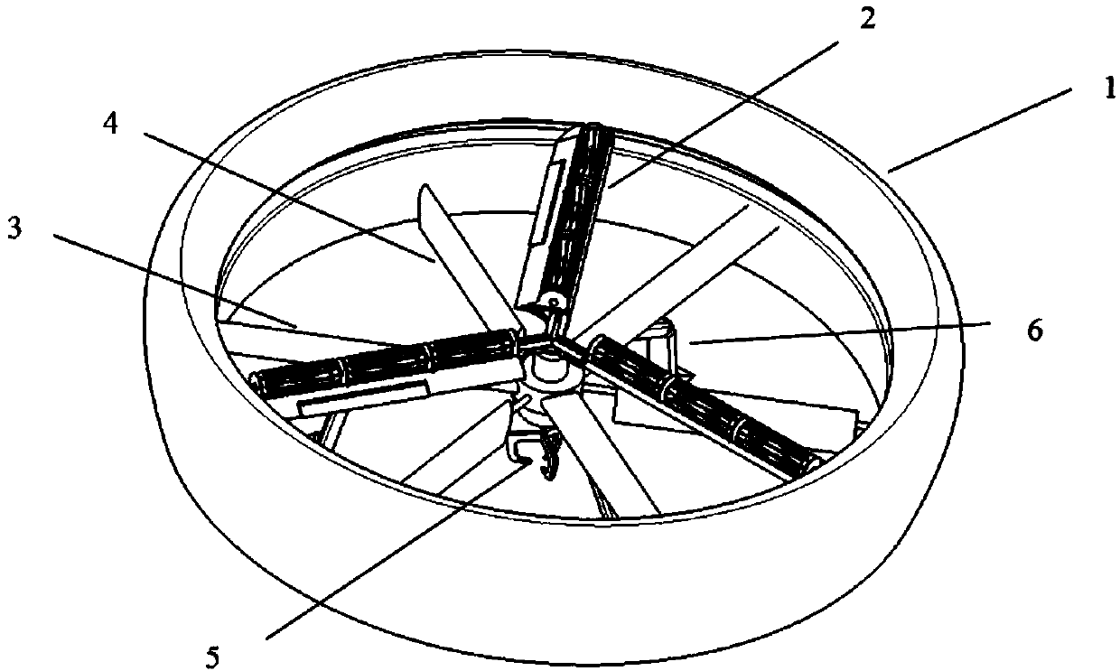
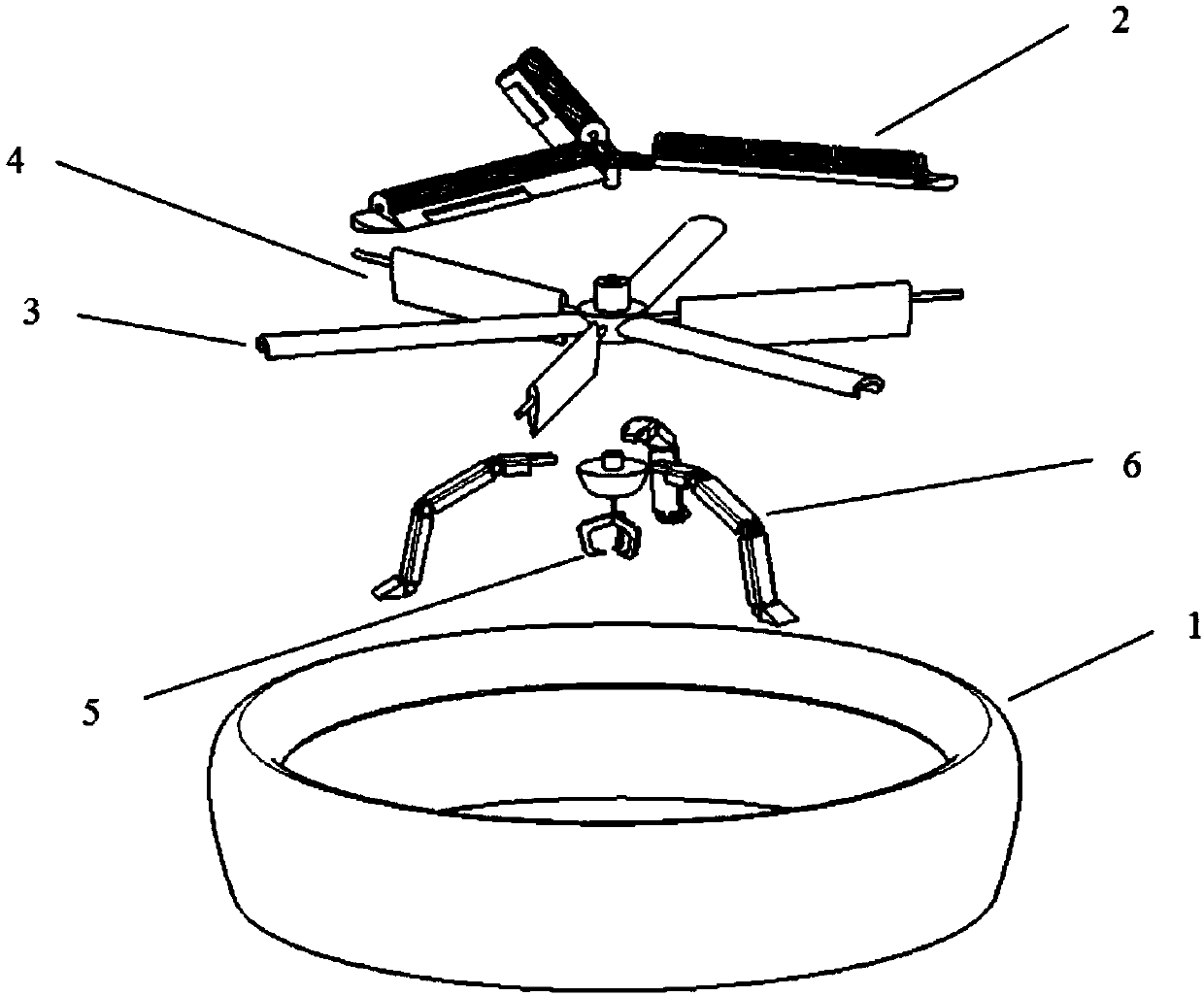
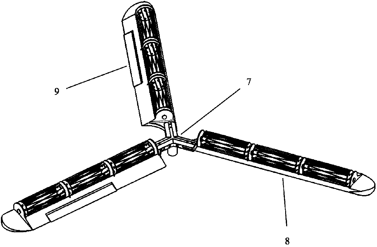
[0031] Such as figure 1 and 2 As shown, the present invention discloses a slotted duct type plume rotor aircraft, comprising a slotted duct, plume rotor, support beam, yaw module, telescopic manipulator and landing gear;

[0032] Such as Figure 6 As shown, the slotted duct is provided with grooves on the inner wall of the duct to suppress the generation of blade tip vortex and reduce the loss of wing tip;

[0033] The supporting beam includes a connecting ring and at least two supporting rods, wherein the connecting ring and the slotted duct are arranged coaxially; the supporting rods are evenly arranged between the connecting ring and the slotted duct, one end and the The connecting ring is fixedly connected, and the other end is fixedly connected to the inner wall of the slotted duct;

[0034] The yaw module...


PUM


Abstract

The invention relates to a notched duct type plume rotor aircraft. The notched duct type plume rotor aircraft comprises a notched duct, a plume rotor, a supporting crossbeam, a yaw rudder surface, a telescopic manipulator and a landing gear, wherein the plume rotor adopts a main lifting force structure; and the notched duct adopts an auxiliary lifting force structure. Through the adoption of the combination form of the notched duct type plume rotor aircraft disclosed by the invention, the lifting force of the aircraft can be improved to a large extent, and an anti-torque cannot be generated; and the notched duct type plume rotor aircraft is very flexible, can be independently used as a module to execute a relevant flight mission such as transporting small-scale objects or executing a monitoring and investigating mission.

Description

technical field [0001] The invention belongs to the field of aviation technology, and mainly relates to a slotted and ducted plume rotor aircraft. Background technique [0002] A general fan-wing aircraft can generate a large low-pressure vortex inside the cross-flow fan through the high-speed rotation of the cross-flow fan at the leading edge of the airfoil, thereby generating a large pressure difference between the upper and lower surfaces of the leading edge of the airfoil, so that the fan wing can fly at a low speed. When generating greater lift, and the exhaust airflow to the trailing edge to generate thrust. The swirl rotor is different from the common fan-wing aircraft, which adopts a rotating fan-wing layout, and uses a power unit to drive the cross-flow fan. Since the fan blades can provide great lift and forward thrust at low speeds, the entire whirl rotor can rotate without being driven by additional power. The biggest difference between the swirl rotor and the ...

Claims


Application Information

Patent Timeline
IPC IPC(8): B64C27/16B64C27/20B64C27/32B64C27/46
CPCB64C27/16B64C27/20B64C27/32B64C27/46B64U10/13B64U50/19B64U50/14
Inventor 雷良徐起肖升兴沙伟
Owner NANJING UNIV OF AERONAUTICS & ASTRONAUTICS
Why Eureka
Try Eureka