Crane provided with suspension end beam trolley and rotating mechanism adopting opening transmission

A rotating mechanism with open technology, which is applied in the direction of walking bridge cranes, cranes, traveling mechanisms, etc., can solve the problems of inability to directly hand over goods in the next workshop, inconvenience, waste of manpower and material resources, etc., to solve the problem of large tonnage small wheel Problems, convenient purchase, and smooth operation

Inactive Publication Date: 2018-02-09
谢新华
View PDF0 Cites 1 Cited by
  • Summary
  • Abstract
  • Description
  • Claims
  • Application Information

AI Technical Summary

Problems solved by technology

[0002] Existing bridge cranes are used in enterprise workshops. Some workshops are equipped with many machine tools for processing and production. Products and raw materials need to be transported to the next workshop or other departments in real time; the hooks of the cranes in the workshop are hung from the trolley. For hoisting goods, the trolley can only run back and forth along the double girders of the crane, and the crane can only run back and forth along the cart rails on the cross columns on both sides of the workshop, so that the range of goods that the crane hook can lift is within the distance between the two cart rails in the workshop. Within the plane surrounded by the two ends, when the goods at the edge of the plane need to be hoisted, the hook will be pulled obliquely, and the items farther away from this plane (such a...

Method used


Image

  • Crane provided with suspension end beam trolley and rotating mechanism adopting opening transmission
  • Crane provided with suspension end beam trolley and rotating mechanism adopting opening transmission
  • Crane provided with suspension end beam trolley and rotating mechanism adopting opening transmission

Examples


Embodiment approach

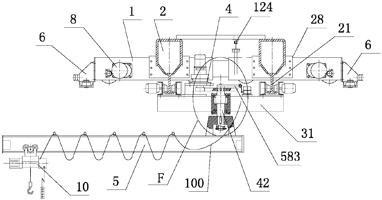
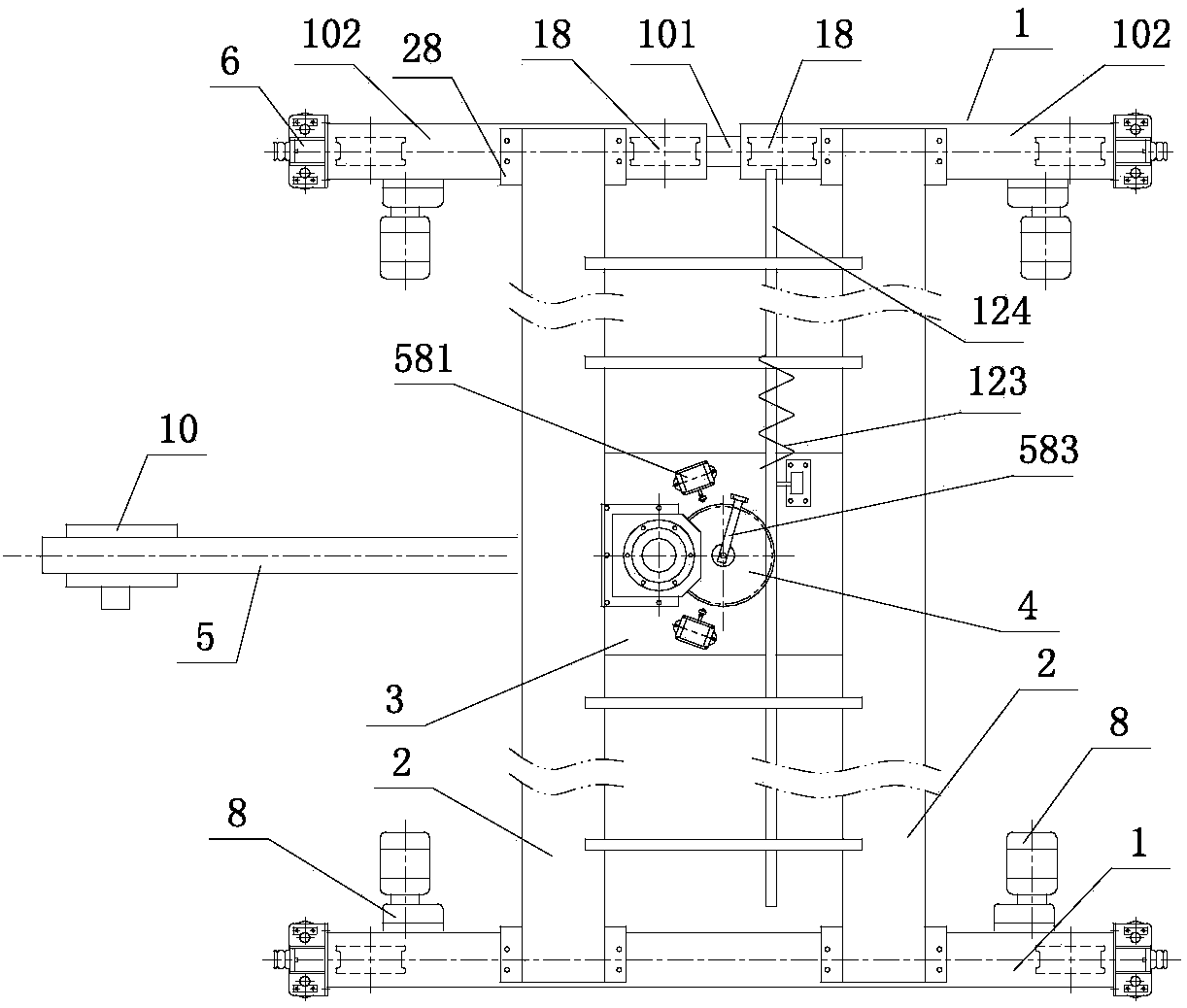
[0038] Such as figure 1 , figure 2 , image 3 , Figure 4 As shown, a crane with a suspended end beam trolley and a rotating mechanism with open transmission includes an end beam 1 and a main beam 2; the end beam 1 is composed of a balanced end beam 102 and a connecting rod 101; A cart driving device 8 and an anti-tipping device 6 are arranged on the beam 1; a track 21 is provided under the main beam 2; a suspended end beam trolley 3 is connected to the track; a rotating mechanism is provided on the suspended end beam trolley 3 4. The middle part of the boom shaft 42 in the rotating mechanism is connected to the thrust bearing 45, and the thrust bearing is connected to the inside of the bearing housing 41, and the boom shaft is connected to the bearing A44 and the bearing B46, and the bearing A and the bearing B The two ends of the above-mentioned bearing seat are respectively connected by the fixed cover 43 and the flange cover 47, and the bearing seat 41 is fixed on the ...


PUM


Abstract

This application discloses a crane with a suspended end beam trolley and a rotating mechanism with open transmission, including an end beam and a main beam; the end beam is composed of a balanced end beam and a connecting rod; Tilting device; there are tracks under the two main beams; the suspended end beam trolley connected to the tracks has a rotating mechanism; the boom shaft is connected to the thrust bearing and bearing A and bearing B; the thrust bearing is connected inside the bearing seat , Bearing A and Bearing B are respectively connected to both ends of the above-mentioned bearing housing through a fixed cover and a flange cover; the driving device is connected to the support of the reducer; the output shaft of the driving device is connected to the pinion, and the pinion is meshed with the large gear. The large gear is connected to the upper part of the boom shaft; the lower part of the boom shaft is connected to the cantilever member; the upper end of the boom shaft is connected to the safety ruler; two travel switches are connected to the small frame; the cantilever beam in the cantilever member is connected to the electric hoist; the cantilever beam It is under the main beam and can be rotated.

Description

technical field [0001] The present application relates to the field of cranes, in particular to a crane with a suspended end beam trolley and a rotating mechanism with open transmission. Background technique [0002] Existing bridge cranes are used in enterprise workshops. Some workshops are equipped with many machine tools for processing and production. Products and raw materials need to be transported to the next workshop or other departments in real time; the hooks of the cranes in the workshop are hung from the trolley. For hoisting goods, the trolley can only run back and forth along the double girders of the crane, and the crane can only run back and forth along the cart rails on the cross columns on both sides of the workshop, so that the range of goods that the crane hook can lift is within the distance between the two cart rails in the workshop. Within the plane surrounded by the two ends, when the goods at the edge of the plane need to be hoisted, the hook will be ...

Claims


Application Information

Patent Timeline
IPC IPC(8): B66C17/04B66C11/10B66C7/16B66C9/10B66C9/14B66C23/84B66C15/00
CPCB66C17/04B66C7/16B66C9/10B66C9/14B66C11/10B66C15/00B66C23/84B66C2700/0342B66C2700/035
Inventor 谢新华
Owner 谢新华
Why Eureka
Try Eureka