Angle adjustment mechanism for fan head

An angle adjustment, fan technology, applied in mechanical equipment, machines/engines, liquid fuel engines, etc., can solve the problems of unadjustable angle, waste of wind power, inflexibility, etc., and achieve the effect of good practicability

Inactive Publication Date: 2018-02-09
XINYI HUIMEI ELECTRICAL APPLIANCES
View PDF0 Cites 3 Cited by
  • Summary
  • Abstract
  • Description
  • Claims
  • Application Information

AI Technical Summary

Problems solved by technology

[0003] The above-mentioned fan head angle adjustment mechanism has the following disadvantages: since the contact surface between the insert piece and the clamp piece is flat, it is difficult to ensure that the clamp piece clamps the insert piece only by the cooperation of nuts and bolts. The fan head suddenly changes from the state of flat blowing or upward blowing to the state of downward blowing
[0004] In addition, the fan head of the traditional floor fan can swing left and right. The swing structure is a set of worm gear system and connecting piece. The worm gear system drives the swinging rotation. The angle range is determined by the length of the connecting piece and the eccentric radius. The length and eccentric radius cannot be changed at will, so the angle cannot be adjusted
The above-mentioned swing structure is not flexible enough in use, sometimes only one or two people blow the fan, but the swing angle of the fan is too large, most of the time it is blowing in a place where there is no one, wasting the wind power

Method used


Image

  • Angle adjustment mechanism for fan head
  • Angle adjustment mechanism for fan head
  • Angle adjustment mechanism for fan head

Examples


Embodiment 1

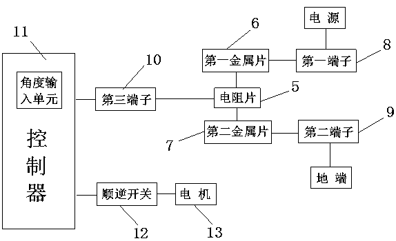
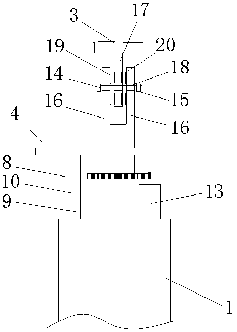
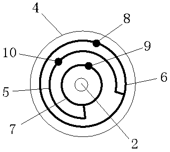
[0027] Such as figure 1 , 2 As shown, the fan head angle adjustment mechanism of this embodiment includes a fan bracket 1 and a fan head 3 mounted on the fan bracket 1 through a rotating shaft 2 (the rotating shaft 2 can rotate on the fan bracket 1), and a motor is fixed on the top of the fan bracket 1 13. The motor shaft of the motor 13 drives the rotating shaft 2 and the fan head 3 on the rotating shaft 2 to rotate through the gear pair; the rotating shaft 2 is equipped with a horizontal disc 4, and the bottom surface of the disc 4 is provided with an arc-shaped Resistance sheet 5, circular first metal sheet 6 and circular second metal sheet 7, described resistance sheet 5, metal sheet are all centered on rotating shaft 2, and resistance sheet 5 is positioned at the first metal sheet 6 and the second Between the metal sheets 7; one end of the resistance sheet 5 is electrically connected to the first metal sheet 6, and the other end is electrically connected to the second me...


PUM


Abstract

The purpose of the present invention is to provide a fan head angle adjustment mechanism, which can easily adjust the pitch angle and rotation angle of the fan head, and reliably fix the fan head at a predetermined pitch angle. The fan head angle adjustment mechanism of the present invention only makes slight changes on the traditional clamping piece and inserting piece, so that the pitch angle of the fan head can be better fixed, and the pitch angle of the fan head can be adjusted very conveniently The present invention also detects the rotation angle of the fan head in real time, and converts the rotation angle into a voltage value and compares it with a predetermined target voltage value, so that when the fan head rotates to a limit angle, the reverse rotation of the fan head is controlled by a forward and reverse switch , to achieve the purpose of reciprocating rotation of the fan head within a predetermined angle range; in summary, the present invention simultaneously realizes the adjustment of the pitch angle and rotation angle of the fan head, and has good practicability.

Description

technical field [0001] The invention belongs to the technical field of fans, and in particular relates to a fan head angle adjustment mechanism. Background technique [0002] The fan head of the traditional floor fan simply uses bolts to adjust its pitch angle. The specific structure is as follows: the top of the bracket is provided with two vertical clamping pieces, and the insert piece at the bottom of the fan head is inserted into the two clamping pieces. between, and then use bolts to pass through the first clamping piece, the insertion piece, and the second clamping piece in turn, and screw the nut on the other end, and adjust the position of the nut to loosen the clamping piece or clamp the insertion piece When the piece is loosened, the pitch angle of the fan head can be adjusted. [0003] The above-mentioned fan head angle adjustment mechanism has the following disadvantages: since the contact surface between the insert piece and the clamp piece is flat, it is diffi...

Claims


Application Information

Patent Timeline
Patent Type & Authority Applications(China)
IPC IPC(8): F04D25/10F04D27/00F04D29/00
CPCF04D25/105F04D27/00F04D29/002
Inventor 李月
Owner XINYI HUIMEI ELECTRICAL APPLIANCES
Why Eureka
Try Eureka