Microwave radar with higher installation efficiency

A technology of microwave radar and installation efficiency, applied in the direction of measuring devices, radio wave measuring systems, instruments, etc., can solve the problems of no protective device, easy to move, difficult and other problems, achieve good heat dissipation effect, not easy to be damaged, The effect of improving stability

Active Publication Date: 2018-02-09
四川嘉义新能有限公司
View PDF6 Cites 4 Cited by
  • Summary
  • Abstract
  • Description
  • Claims
  • Application Information

AI Technical Summary

Problems solved by technology

[0003] The technical problem to be solved by the present invention is that usually radars are installed in a certain place outdoors to work, but radars are usually placed directly in a certain place during normal operation, and there is no protective device around them, so it is very difficult to It is vulnerable to external damage or environmental interference, which affects its service life. Second, its position is not fixed and it is easy to move. Finally, the limitation of its own working principle makes it difficult to install it in a fixed place. Large, the purpose is to provide a microwave radar that can improve installation efficiency, so that the radar can be quickly installed in a fixed place, improve stability, and be difficult to be moved or stolen by others. At the same time, it can be used for outdoor microwave radar Play a good role in protection, while improving its stability, not easy to be damaged, and according to the use of the radar or the external environment, it can make the radar switch the working state, thereby greatly improving its outdoor safety, and the heat dissipation effect is good. Ensure the normal operation of the microwave radar

Method used


Image

  • Microwave radar with higher installation efficiency

Examples


Embodiment

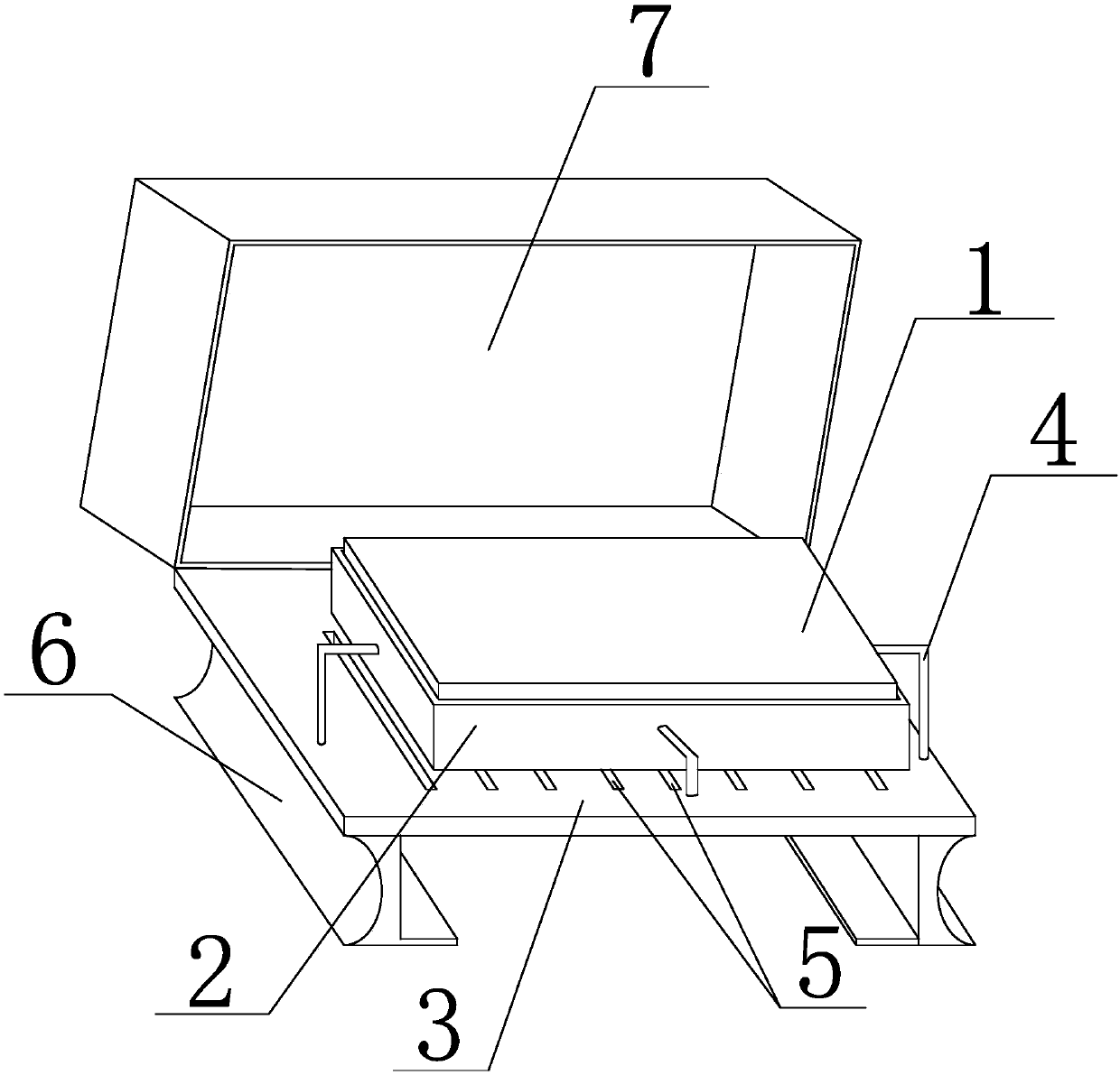
[0022] Such as figure 1 As shown, the microwave radar capable of improving the installation efficiency of the present invention includes a microwave radar body 1, the microwave radar body 1 is sleeved in a protective box 2, the upper opening of the protective box 2 is provided with cooling holes on the bottom surface, and the protective box 2 A fixed plate 3 is provided below, and the surroundings of the protective box 2 are connected with the fixed plate 3 through the fixed pole 4. The fixed plate 3 is provided with a plurality of ventilation slots 5 running through the upper and lower sides of the fixed plate 3, and the ventilation slots 5 are located in the protective box. 2, the lower two ends of the fixed plate 3 are respectively connected with the mounting plate 6, one side of the mounting plate 6 is L-shaped, the vertical plate of the 6L type of the mounting plate is vertically connected with the fixed plate 3, and the horizontal plate of the 6L type of the mounting plat...


PUM


Abstract

The invention discloses a piece of microwave radar with higher installation efficiency. The microwave radar includes a microwave radar body which is sheathed in a protection box. The protection box isprovided with cooling holes in the bottom. A fixed plate is arranged under the protection box. The four sides of the protection box are connected with the fixed plate through fixed support rods. Thefixed plate is provided with a plurality of ventilation slots. Each of the two ends of the bottom of the fixed plate is connected with a mounting plate of which one side is L-shaped and the other sideis semicircular. The mounting plates and the fixed plate are connected through connecting devices. The microwave radar of the invention can be quickly installed in a fixed place, so that the microwave radar is more stable and cannot be easily moved or stolen by others. The microwave radar can be well protected when installed outdoors. The stability of the microwave radar is improved, and the microwave radar is not easy to damage. Moreover, the radar can be switched between different working states according to the use state or the external environment, and therefore, the safety in outdoor useis greatly improved.

Description

technical field [0001] The invention relates to a microwave radar, in particular to a microwave radar capable of improving installation efficiency. Background technique [0002] Radar is a transliteration of English Radar, derived from the abbreviation of radio detection and ranging, meaning "radio detection and ranging", that is, to use radio methods to find targets and determine their spatial positions. Therefore, radar is also called "radiolocation". Radar is an electronic device that uses electromagnetic waves to detect objects. The radar emits electromagnetic waves to irradiate the target and receives its echo, thereby obtaining information such as the distance from the target to the electromagnetic wave emission point, the distance change rate (radial velocity), azimuth, and height. Microwaves are radio waves with very short wavelengths. Microwaves have good directivity and their speed is equal to the speed of light. When the microwave meets the vehicle, it is refle...

Claims


Application Information

Patent Timeline
Patent Type & Authority Applications(China)
IPC IPC(8): G01S7/02
CPCG01S7/02G01S7/027
Inventor 杨浩
Owner 四川嘉义新能有限公司
Why Eureka
Try Eureka