Mechanism for clamping cable

A network cable and limit mechanism technology, which is applied to the parts of the connection device, overhead line/cable equipment, coupling device, etc., can solve the problem that the network cable connected to the router is not properly protected, and the crystal head network port and crystal head are damaged. Easy to rotate, easy to operate, and reduce friction

Inactive Publication Date: 2018-02-09
CHENGDU HONGSHAN TECH
View PDF7 Cites 4 Cited by
  • Summary
  • Abstract
  • Description
  • Claims
  • Application Information

AI Technical Summary

Problems solved by technology

[0005] The purpose of the present invention is to provide a mechanism for clamping the network cable to solve the problem that the network cable connected to the router is not properly protected in the prior art. Detachment, causing network interruption, or even damaging the crystal head or the network port on the router

Method used


Image

  • Mechanism for clamping cable
  • Mechanism for clamping cable

Examples


Embodiment 1

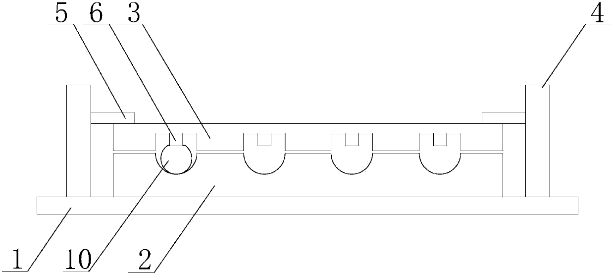
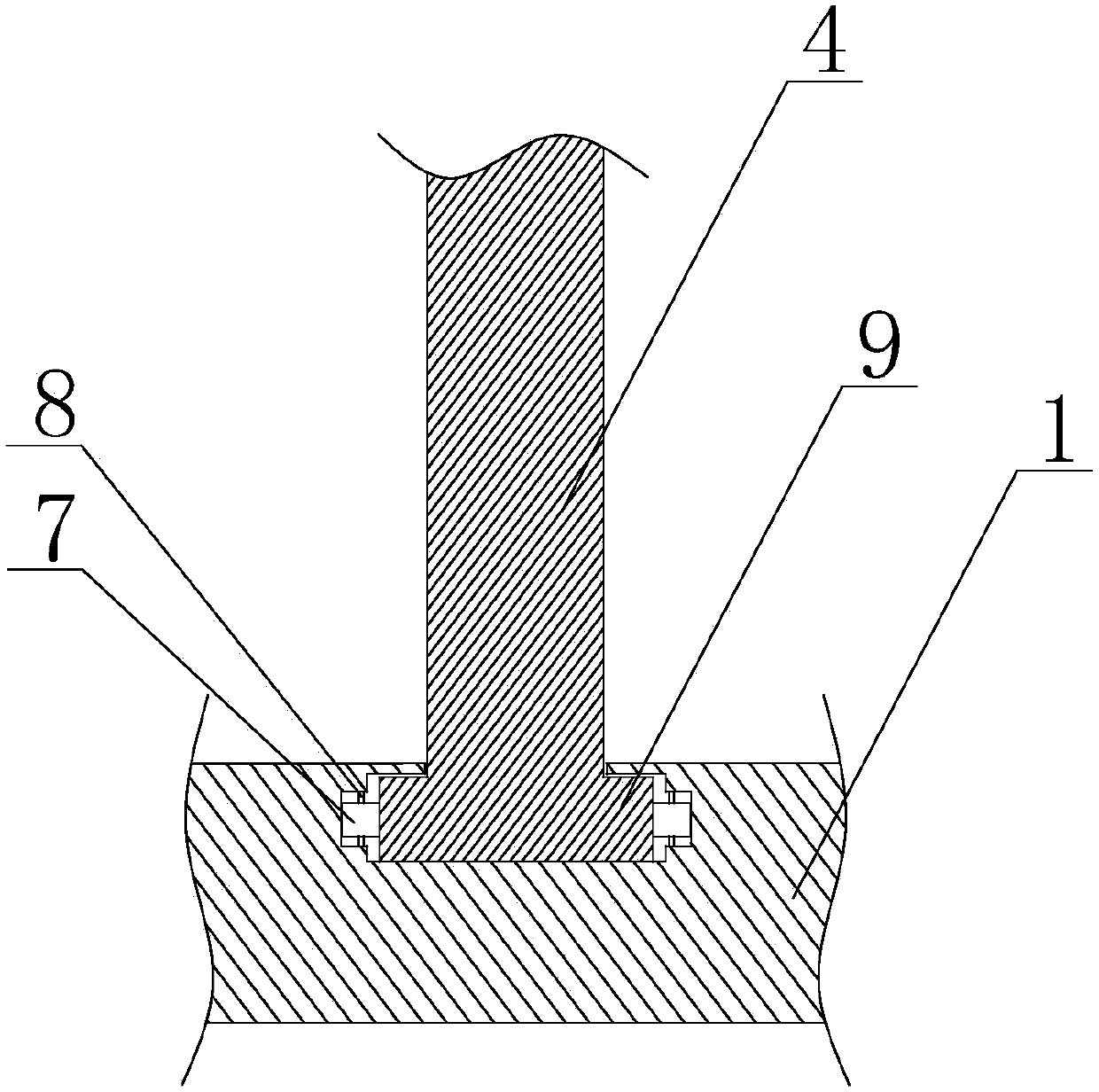
[0027] like figure 1 and figure 2The shown mechanism for clamping the network cable includes a base 1, on which a pay-off plate 2 is fixed, four first grooves are arranged on the pay-off plate 2, and two limit mechanisms are installed on the base 1, The limit mechanism is respectively located on both sides of the pay-off plate 2, and the limit mechanism can rotate around its central axis perpendicular to the horizontal plane; it also includes a pressure plate 3, which is provided with 4 grooves that match the first groove. The second groove, the second groove is provided with a crimping block 6, the thickness of the crimping block 6 is configured so that when the crimping plate 3 is located below the limit mechanism, the crimping block 6 squeezes the second The network cable 10 in the groove; the base 1 is provided with an accommodating cavity, the limit mechanism includes a rotating column 4 and a limiting plate 5 arranged on the rotating column 4, and the bottom end of the...


PUM


Abstract

The invention discloses a mechanism for clamping a cable. The mechanism comprises a base, wherein a paying-off plate is fixedly arranged on the base; M first grooves are formed in the paying-off plate, and M is a positive integer; two limiting mechanisms are mounted on the base; the limiting mechanisms are positioned on two sides of the paying-off plate respectively; and the limiting mechanisms can rotate around the central axes, vertical to the horizontal plane, of the limiting mechanisms. The mechanism also comprises a cable pressing plate; M second grooves matched with the first grooves areformed in the cable pressing plate; each second groove is internally provided with a cable pressing block; and the thickness of each cable pressing block is such configured that, when the cable pressing plate is positioned below the limiting mechanisms, each cable pressing block is used for squeezing the cable in the corresponding groove. According to the mechanism, by clamping the cable, when the cable is pulled, a crystal plug cannot fall off from the internet access of a router, and the damage of the crystal plug or the internet access of the router cannot be caused; and moreover, the device is convenient and quick in operation, the cable can be compressed firmly, and the step of mounting or dismounting the cable pressing plate is extremely simple.

Description

technical field [0001] The invention relates to the field of clamping network cables, in particular to a mechanism for clamping network cables. Background technique [0002] In today's home or office, routers are an essential communication device. [0003] Usually, a network cable is connected to the router to connect to the RJ45 interface on the wall. Since the coverage of the wireless network is affected by terrain factors such as doors and walls in the application area, in order to ensure the data transmission speed, the router and the application terminal such as the network port on the computer are also connected through a network cable. Therefore, at least one network cable is usually connected to the router, and in many cases, all the mesh holes on the router may be plugged with network cables. [0004] During use, if the network cable is pulled, for example, the network cable placed on the ground is accidentally kicked, or it is entangled with the network cable, an...

Claims


Application Information

Patent Timeline
Patent Type & Authority Applications(China)
IPC IPC(8): H01R13/639H02G1/04
CPCH01R13/639H01R13/6395H02G1/04
Inventor 黄友华
Owner CHENGDU HONGSHAN TECH
Why Eureka
Try Eureka