
Millimeter wave fast pulse reflection over-large real-time protective circuit and protection method thereof

A technology of pulse reflection and protection circuit, applied in the layout of amplifier protection circuit, etc., can solve the problems of slow rising and falling edges of the detection module, unsuitable for pulse signals, unsuitable for narrow pulses, etc., to reduce signal interference, suppress clutter signals, cost reduction effect

Pending Publication Date: 2018-02-09
合肥雷科电子科技有限公司
View PDF0 Cites 0 Cited by
  • Summary
  • Abstract
  • Description
  • Claims
  • Application Information

AI Technical Summary

Problems solved by technology

The existing excessive reflection wave protection circuit mainly uses "forward and reverse detection + voltage amplification and delay + positive and negative voltage comparison" to protect the excessive reflection signal. When the ratio of the reverse voltage to the forward voltage exceeds a certain value Finally, start the protection. This protection method has the following disadvantages: 1. The rising and falling edges of the traditional detection module are slow, which is not suitable for narrow pulses; 2. The delay circuit of the traditional detection module will lead to unsuitable pulse signals or variable duty 3. The traditional analog detection and protection circuit requires more components, higher cost and longer response time

Method used


Image

  • Millimeter wave fast pulse reflection over-large real-time protective circuit and protection method thereof
  • Millimeter wave fast pulse reflection over-large real-time protective circuit and protection method thereof
  • Millimeter wave fast pulse reflection over-large real-time protective circuit and protection method thereof

Examples


Embodiment Construction

[0029] The present invention will be further described below in conjunction with accompanying drawing:

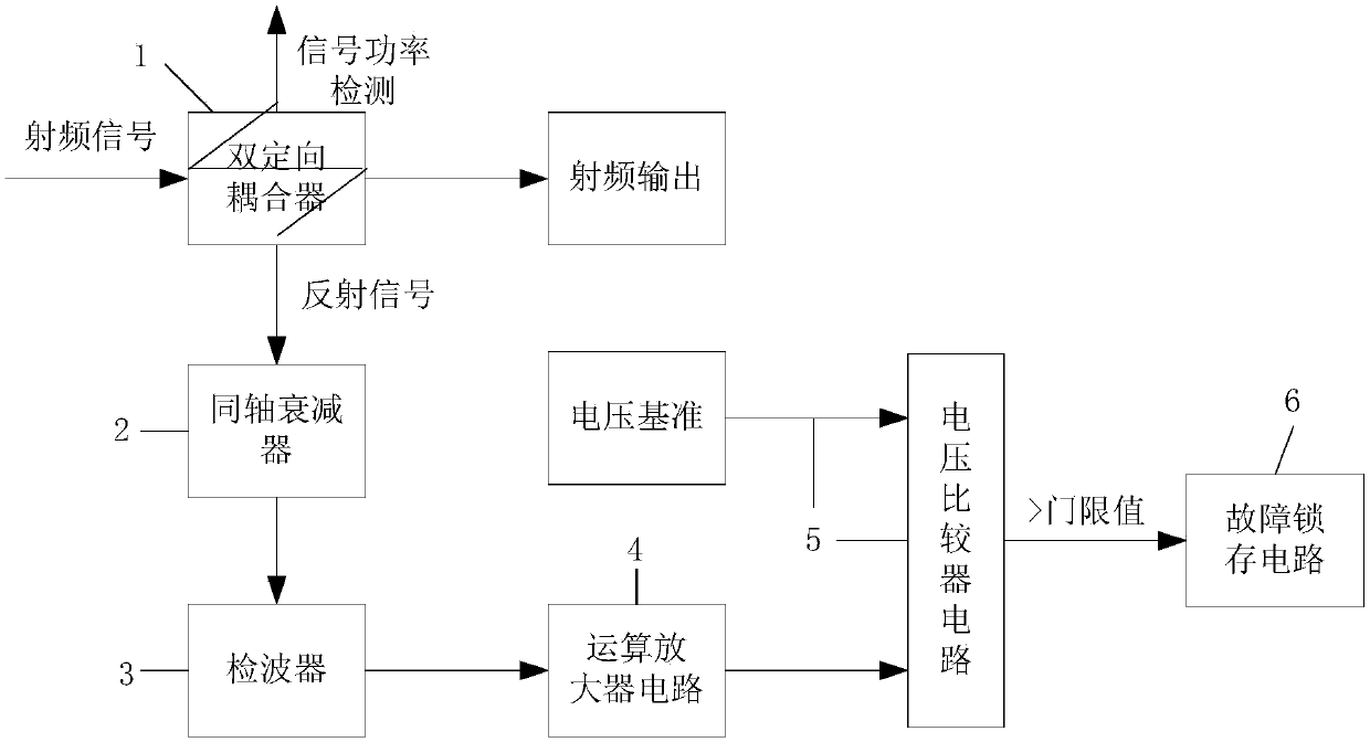
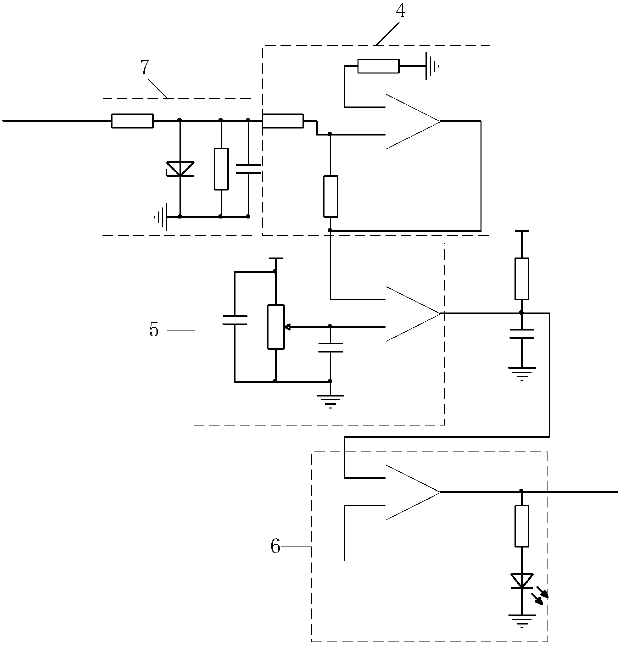
[0030] Such as Figure 1-Figure 2 The shown real-time protection circuit for excessive reflection of millimeter wave fast pulses includes a dual directional coupler 1 , a coaxial attenuator 2 , a detector 3 , an operational amplifier circuit 4 , a voltage comparison circuit 5 and a fault latch circuit 6 .

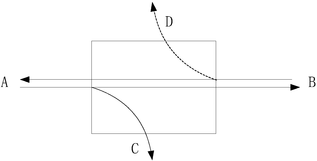
[0031] The dual directional coupler 1, its positive input terminal is connected to the radio frequency input signal, its forward output terminal is connected to the radio frequency output, its forward coupling terminal is connected to the power detection circuit, and its reverse coupling terminal is connected to the input terminal of the coaxial attenuator . The output terminal of the detector 3 is connected to the input terminal of the operational amplifier circuit 4 . The output terminal of the operational amplifier circuit 4 is connected to the input terminal of the...


PUM


Abstract

The invention relates to a millimeter wave fast pulse reflection over-large real-time protective circuit and protection method thereof. The protective circuit comprises a dual-directional coupler, a coaxial attenuator, a wave detector, an operational amplifier circuit, a voltage comparison circuit and a fault latching circuit; the positive input of the dual-directional coupler is connected with aradio frequency input signal, the positive output is connected with the radio frequency output, the positive coupling end is connected with a power detection circuit, and the negative coupling end isconnected with the input end of the coaxial attenuator; the output end of the coaxial attenuator is connected with the input end of the wave detector; the output end of the wave detector is connectedwith the input end of the operational amplifier circuit; the output end of the operational amplifier circuit is connected with the input end of the voltage comparison circuit; and the output end of the voltage comparison circuit is connected with the input end of the fault latching circuit. By using the protective circuit disclosed by the invention, the disadvantage in the prior art can be solved,and the power amplifier system can be protected in real time when the reflection signal t the power amplifier output end is over-large.

Description

technical field [0001] The invention relates to the technical field of power amplifier systems, in particular to a real-time protection circuit and a protection method for excessive reflection of millimeter-wave fast pulses. Background technique [0002] In a microwave system, in the actual circuit application of a power amplifier with an output power exceeding 2W, due to open circuit, short circuit, or mismatch of the load, the output port of the power amplifier presents a relatively high reflection signal distribution, so that the RF energy cannot be effectively transmitted out, resulting in a large Part of the energy is converted into heat energy, resulting in heat accumulation, which reduces the efficiency of the power amplifier on the one hand, and on the other hand, will cause successful heat release and burnout. Therefore, it is necessary to protect the power amplifier system from excessive reflected signals. The existing excessive reflection wave protection circui...

Claims


Application Information

Patent Timeline
IPC IPC(8): H03F1/52
CPCH03F1/52
Inventor 李运海贾义
Owner 合肥雷科电子科技有限公司
Learn More