Ethernet signal scheduling method and device and system

A signal scheduling and Ethernet technology, applied in the network field, can solve the problems of multiple devices and complex network systems

Active Publication Date: 2018-02-09
ZHUHAI JINGWEI TIANDI COMM TECH CO LTD
View PDF9 Cites 3 Cited by
  • Summary
  • Abstract
  • Description
  • Claims
  • Application Information

AI Technical Summary

Problems solved by technology

[0006] The embodiment of the present application provides an Ethernet signal scheduling method, device and system to solve the problems in the prior art that there are many equipments in the Ethernet signal scheduling process and the network system is relatively complicated.

Method used


Image

  • Ethernet signal scheduling method and device and system
  • Ethernet signal scheduling method and device and system
  • Ethernet signal scheduling method and device and system

Examples


Embodiment 1

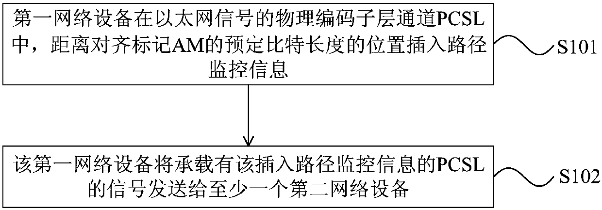
[0116] figure 1 It is a flow chart of the Ethernet signal transmission method provided in Embodiment 1 of the present application. The method in this embodiment is applicable to the situation where one network device transmits Ethernet signals to one or more network devices. The method is executed by the first network device, and the device is usually implemented in hardware and / or software. Such as figure 1 As shown, the method of the present embodiment includes the following steps:

[0117] Step 101 , the first network device inserts path monitoring information at a predetermined bit length away from the alignment mark AM in the physical coding sublayer channel PCSL of the Ethernet signal.

[0118] Step 102, the first network device sends the PCSL signal carrying the insertion path monitoring information to at least one second network device.

[0119] The Ethernet signal of the MLD structure includes multiple physical coding sublayer lanes (Physical Coding Sublayer Lane,...

Embodiment 2

[0137] On the basis of the above solutions, the embodiments of the present application further provide an Ethernet signal transmission method.

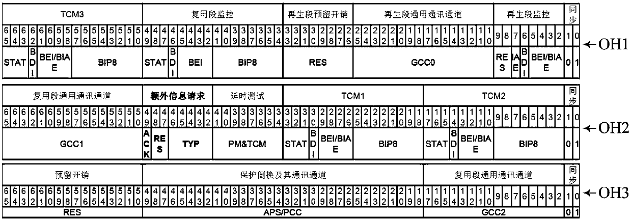
[0138] Wherein, the path monitoring information is carried by an overhead bit block, and the overhead bit block includes at least one bit block.

[0139] Specifically, the path monitoring information is carried by an overhead (Overhead, OH for short) bit block, which may be carried by information bits of the overhead bit block. The bit number and structure of the OH bit block may be consistent with other bit blocks in the Ethernet signal, such as a data bit block and a control bit block. That is to say, the OH bit block can also be 66 bits, including 64 bits of overhead information bits and 2it synchronization header bits. Wherein, the 64-bit overhead information bits may be 8 octets, Octet0-Octet7.

[0140] The path monitoring information includes the RS overhead of the regenerating section, and the RS overhead is used to monitor t...

Embodiment 3

[0165] The embodiment of the present application also provides a method for transmitting an Ethernet signal. Figure 5 It is a flow chart of the Ethernet signal transmission method provided in the third embodiment of the present application. Such as Figure 5 As shown, in step 101 of the above solution, the first network device inserts path monitoring information at a predetermined bit length away from AM in the PCSL of the Ethernet signal, specifically including:

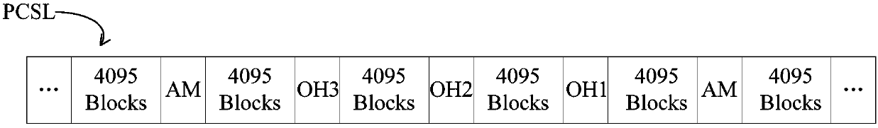
[0166] Step 501 , the first network device inserts the path monitoring information in the PCSL of the Ethernet signal at a position of the predetermined bit length away from each AM.

[0167] The Ethernet signal has different PCSLs according to its transmission rate, and each PCSL includes multiple AMs. It should be noted that no matter how many AMs there are in the PCSL of the Ethernet signal, any two adjacent AMs are separated by a fixed number of bits, such as 16383 bit blocks. Inserting the path information ...


PUM


Abstract

The embodiment of the invention provides an ethernet signal scheduling method and device and a system. The ethernet signal scheduling method comprises the steps that first network equipment performs PCSL exchange on M paths of electric signals so as to generate N paths of ethernet signals or N paths of client signals, wherein M>=1, N>=1 and M and N cannot be 1 at the same time; the first network equipment transmits N paths of ethernet signals to at least one set of second network equipment; or the first network equipment transmits N paths of client signals to at least one set of first media access control MAC processing equipment. PCSL exchange is performed on M paths of electric signals to realize signal scheduling and the scheduled signals are transmitted to the corresponding network equipment or MAC processing equipment so that the ethernet signals can be effectively scheduled.

Description

[0001] This application was filed on January 14, 2014. The application number is: 201480000208.1, and the application name is: a divisional application of Ethernet signal transmission method, scheduling method, device and system thereof. technical field [0002] The embodiments of the present application relate to network technologies, and in particular to an Ethernet signal scheduling method, device and system. Background technique [0003] With the rapid development of network technology, people have higher and higher requirements on the transmission rate and quality of network data. At present, for high-speed Ethernet, a multi-lane (MLD) structure is generally adopted. How to effectively transmit the Ethernet signal of the MLD structure is an important requirement. Effective transmission includes two aspects. One is reliable Transmission, and the second is effective scheduling. [0004] In the prior art, an Optical Transport Network (OTN) is used to efficiently transmit ...

Claims


Application Information

Patent Timeline
Patent Type & Authority Applications(China)
IPC IPC(8): H04L12/26H04L1/00H04J3/16
CPCH04J3/1652H04L1/0006H04L1/0057H04L43/0811H04L47/822H04L69/12
Inventor 操时宜
Owner ZHUHAI JINGWEI TIANDI COMM TECH CO LTD
Why Eureka
Try Eureka