Reinforcement Cage Skeleton Forming Device for Pile Hole Foundation

A forming device and reinforcement cage technology, applied in the field of building construction, can solve the problems that the strength of pile holes cannot meet the requirements of building construction, the effect of transverse rib welding is not ideal, and the distribution of transverse ribs is uneven, so as to avoid swing and radial swing Eliminate and improve the effect of distribution uniformity

Inactive Publication Date: 2019-05-03
宜昌市洋坤建筑有限公司
View PDF10 Cites 0 Cited by
  • Summary
  • Abstract
  • Description
  • Claims
  • Application Information

AI Technical Summary

Problems solved by technology

[0003] According to the depth of the pile hole, the axial length of the general steel cage is the same as the depth of the pile hole. However, when pouring a pile hole with a relatively long depth, the construction personnel usually splice multiple steel cages of equal length, and then hoist them to In the pile hole, concrete is poured at the end to shorten the construction time; however, since there are many longitudinal bars on the steel cage and they are distributed in a circle, that is, each longitudinal bar needs to be fixed one by one during production to complete the horizontal alignment. Helical winding and welding of ribs; however, the existing fixing parts tend to move relative to the longitudinal ribs when the horizontal ribs are wound, which leads to uneven distribution of the transverse ribs and unsatisfactory welding effect of the transverse ribs. Moreover, when the steel cage is hoisted , the transverse reinforcement is easy to separate from the longitudinal reinforcement, and eventually the strength of the pile hole after pouring cannot meet the construction requirements

Method used


Image

  • Reinforcement Cage Skeleton Forming Device for Pile Hole Foundation
  • Reinforcement Cage Skeleton Forming Device for Pile Hole Foundation
  • Reinforcement Cage Skeleton Forming Device for Pile Hole Foundation

Examples


Embodiment 1

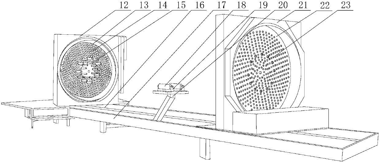
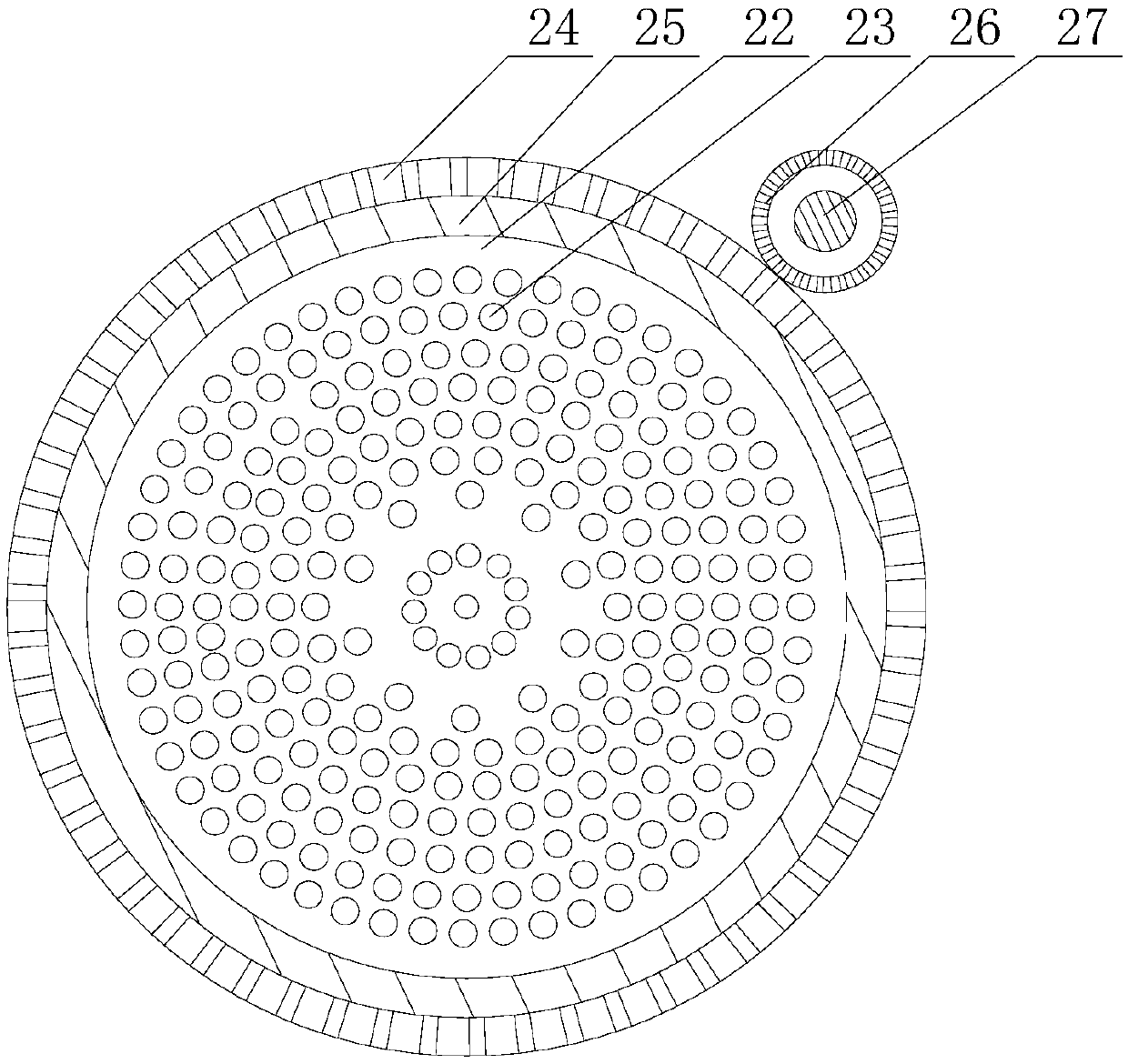
[0029] Such as Figure 1~5 As shown, the present embodiment includes a base 17, a guide rail 16 is provided in the middle of the base 17, the first support plate 12 is fixed on one end of the guide rail 16, and the second support plate 21 is slidably arranged on the other end of the guide rail 16. A first turntable 13 is rotated on the first support plate 12, and a plurality of butt holes 14 are opened on the first turntable 13. The plurality of butt holes 14 are radially distributed outward along the radial direction of the first turntable 13. Two coaxial bearings 25 are rotatably arranged on the second support plate 21, and there is a gap between the two bearings 25, and the second turntable 22 opposite to the first turntable 13 is rotatably arranged in the two bearings 25. , and an annular toothed belt 24 is provided in the middle of the outer peripheral wall of the second turntable 22, and the toothed belt 24 extends outwards after passing through the gap, and a motor is f...

Embodiment 2

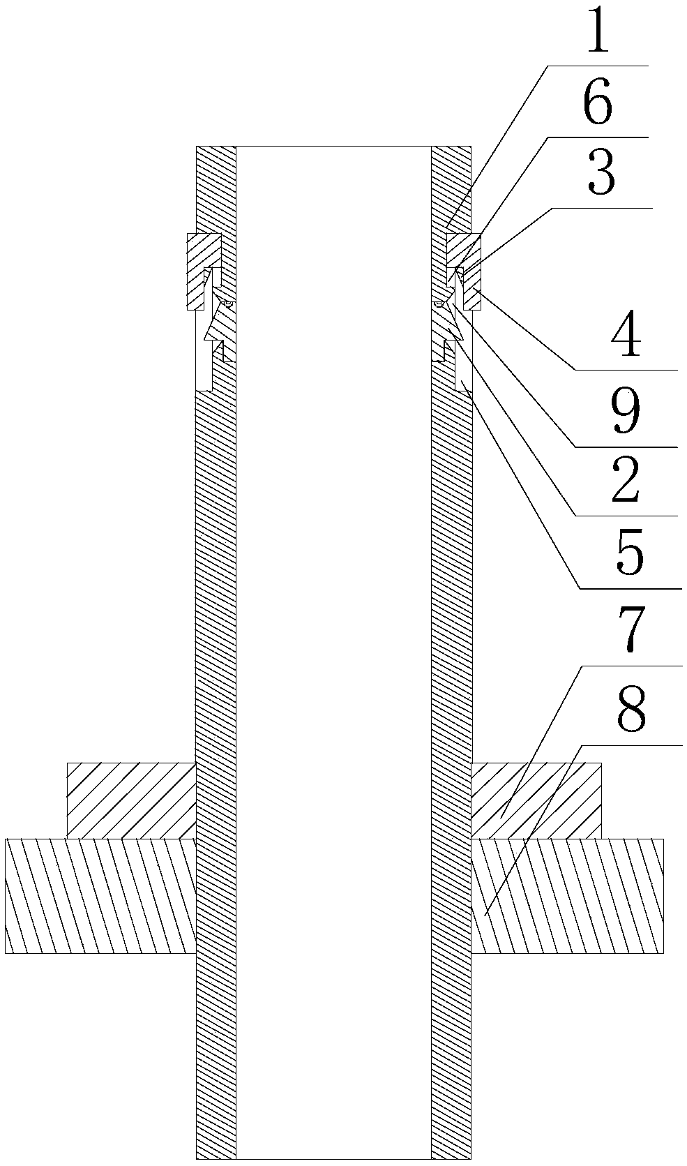
[0034] Such as Figure 1~5 As shown, in this embodiment, transition arcs 11 are respectively provided on both sides of the contact block 10. When the pressure block 2 rotates along the circumferential direction of the annular groove 9 to contact with the contact block 10, the inner side wall of the pressure block 2 and the A smooth transition is realized between the outer side walls of the contact block 10 . When the pressure ring 4 is adjusted to be in contact with the outer side wall of the contact block 10, since the inner peripheral wall of the protrusion 3 is smooth, the two ends of the contact block 10 on the circumferential track of the limit groove 5 are likely to collide with the inner peripheral wall of the protrusion 3. Scratching causes the protrusion 3 to be damaged, so that the adjustment accuracy of the protrusion 3 in the later period is reduced. For this, the applicant sets excessive arcs at the two ends of the protrusion 3, so that the inner wall of the protr...


PUM


Abstract

The invention discloses a reinforcement cage forming device for a pile hole foundation. The reinforcement cage forming device comprises a base and a plurality of fixing components and is characterizedin that the middle of the base is provided with a guide rail, a first support plate is fixed at one end of the guide rail, a second support plate is slidably arranged at the other end of the guide rail, a first rotary disc is rotatably arranged on the first support plate and provided with a plurality of butt joint holes, the second support plate is rotatably provided with two coaxial bearings, agap exists between the two bearings, a second rotary disc opposite to the first rotary disc is rotatably arranged in the two bearings, the middle of the outer peripheral wall of the second rotary discis provided with a toothed belt, a motor is fixed on the second support plate, a gear is mounted at the output end of the motor, and the second rotary disc is provided with a plurality of fixing holes. The reinforcement cage forming device has the advantages that during winding, longitudinal reinforcing steel bars are constantly clamped and fixed by the fixing components, a welding effect betweenthe longitudinal reinforcing steel bars and transverse reinforcing steel bars is prevented from being affected by the fact that the longitudinal reinforcing steel bars turn in barrels, and the strength of a reinforcement cage is guaranteed.

Description

technical field [0001] The invention relates to the field of building construction, in particular to a reinforcement cage skeleton forming device for pile hole foundations. Background technique [0002] During the construction of bridges, culverts or high-rise buildings, the foundation may be piled according to requirements. The method is to use machine punching and water mill drilling, and the hole depth meets the design requirements, and then lower the reinforcement cage to the pile hole, and then insert the conduit for concrete pouring . And when the concrete structure is a columnar or strip-shaped member, the central part does not need to be reinforced, and only the reinforcement is arranged under the surface of the concrete member that contacts the air. If the component is independent, it is necessary to prefabricate the reinforcement around the component during construction, and usually the prefabricated reinforcement structures such as bored piles, excavated piles, a...

Claims


Application Information

Patent Timeline
Patent Type & Authority Patents(China)
IPC IPC(8): B21F27/20
CPCB21F27/20
Inventor 杨蒙蒙
Owner 宜昌市洋坤建筑有限公司
Why Eureka
Try Eureka