A kind of application method of clamping component for prefabrication of reinforcement cage of building foundation

A technology of clamping components and application method, applied in the field of construction, can solve the problems of uneven distribution of transverse ribs, detachment of transverse ribs, and unsatisfactory welding effect of transverse ribs, and achieves the advantages of ensuring strength, uniform distribution, and improving the scope of application. Effect

Active Publication Date: 2019-01-25
振中建设集团有限公司
View PDF7 Cites 0 Cited by
  • Summary
  • Abstract
  • Description
  • Claims
  • Application Information

AI Technical Summary

Problems solved by technology

[0003] According to the depth of the pile hole, the axial length of the general steel cage is the same as the depth of the pile hole. However, when pouring a pile hole with a relatively long depth, the construction personnel usually splice multiple steel cages of equal length, and then hoist them to In the pile hole, concrete is poured at the end to shorten the construction time; however, since there are many longitudinal bars on the steel cage and they are distributed in a circle, that is, each longitudinal bar needs to be fixed one by one during production to complete the horizontal alignment. Helical winding and welding of ribs; however, the existing fixing parts tend to move relative to the longitudinal ribs when the horizontal ribs are wound, which leads to uneven distribution of the transverse ribs and unsatisfactory welding effect of the transverse ribs. Moreover, when the steel cage is hoisted , the transverse reinforcement is easy to separate from the longitudinal reinforcement, and eventually the strength of the pile hole after pouring cannot meet the construction requirements

Method used


Image

  • A kind of application method of clamping component for prefabrication of reinforcement cage of building foundation
  • A kind of application method of clamping component for prefabrication of reinforcement cage of building foundation
  • A kind of application method of clamping component for prefabrication of reinforcement cage of building foundation

Examples


Embodiment 1

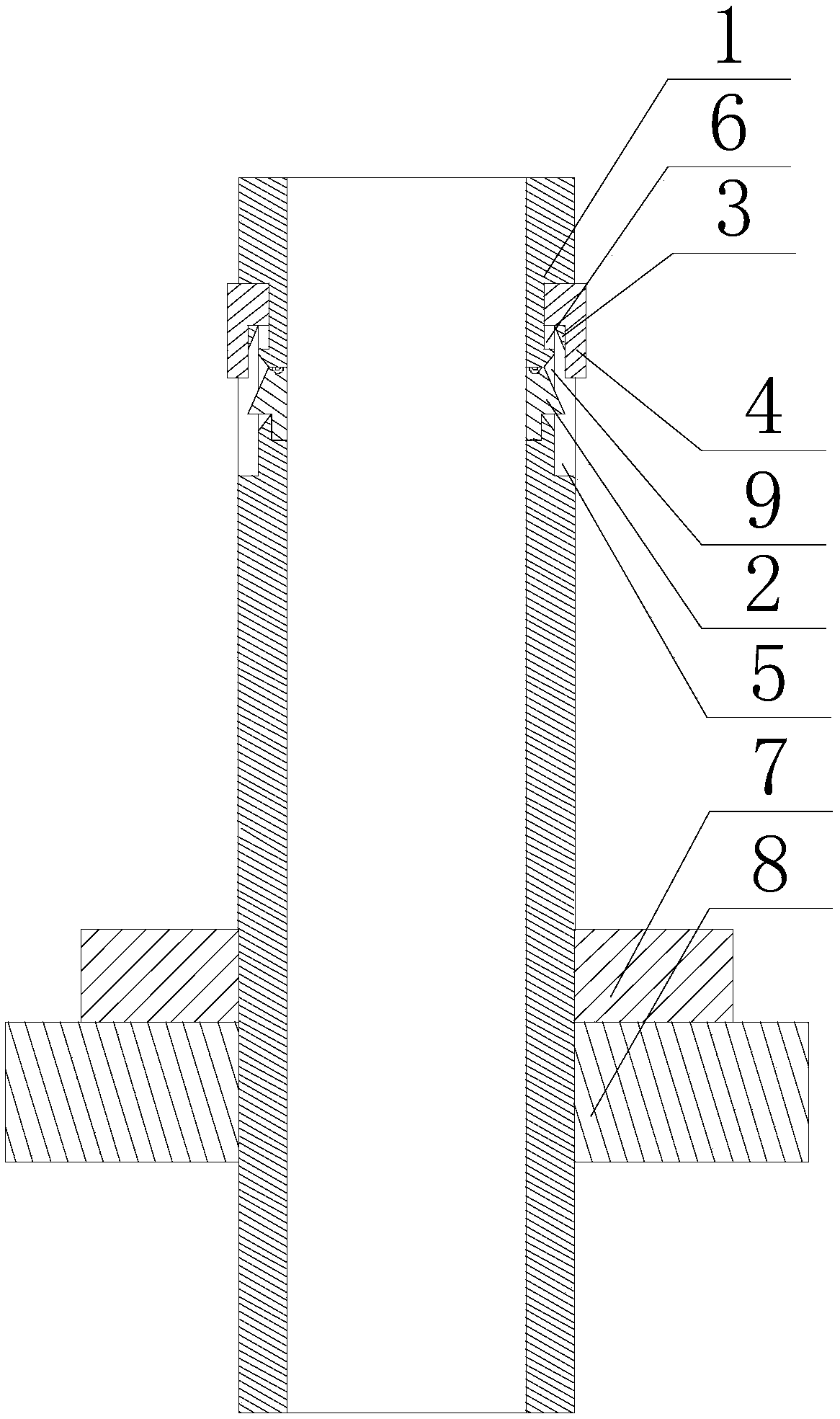
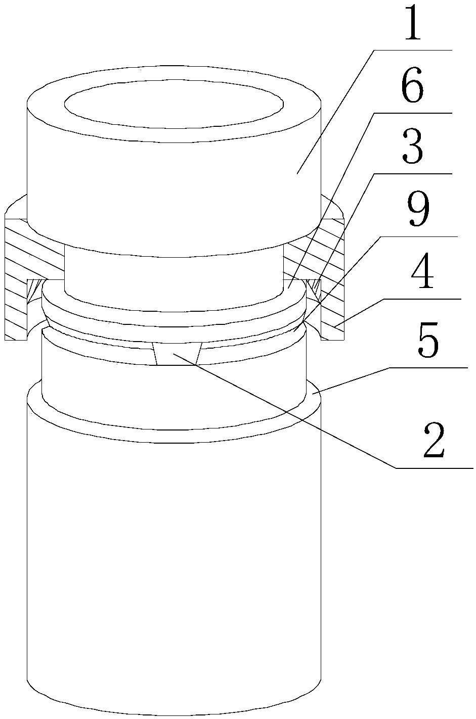
[0024] Such as Figure 1~3As shown, this embodiment includes the following steps: firstly, two opposite cylinders respectively act on the two ends of a longitudinal rib, and one end of the cylinder penetrates the installation hole on the turntable, and ensures that the snap ring and the nut are installed respectively. At both ends of the hole, tighten the nuts so that the cylinder is fastened on the turntable, then align the end of the longitudinal rib with the axis of the cylinder until the end of the longitudinal rib is inserted into the cylinder, and rotate the pressure ring to make it along the cylinder The axis of the body moves towards the direction of the snap ring, so that the oblique contact block on the pressure block contacts the inner side wall of the annular protrusion, and the protrusion presses the contact block, so that the inner side wall of the pressure block approaches the axis of the cylinder , to realize the extrusion of the inner wall of the briquetting b...

Embodiment 2

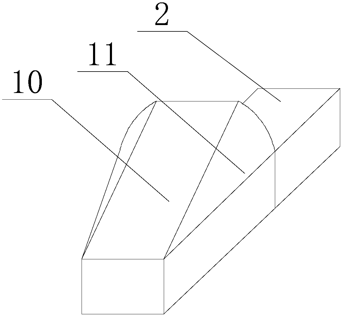
[0029] Such as Figure 1~3 As shown, in this embodiment, transition arcs 11 are respectively provided on both sides of the contact block 10. When the pressure block 2 rotates along the circumferential direction of the annular groove 9 to contact with the contact block 10, the inner side wall of the pressure block 2 and the A smooth transition is realized between the outer side walls of the contact block 10 . When the pressure ring 4 is adjusted to be in contact with the outer side wall of the contact block 10, since the inner peripheral wall of the protrusion 3 is smooth, the two ends of the contact block 10 on the circumferential track of the limit groove 5 are likely to collide with the inner peripheral wall of the protrusion 3. Scratching causes the protrusion 3 to be damaged, so that the adjustment accuracy of the protrusion 3 in the later period is reduced. For this, the applicant sets excessive arcs at the two ends of the protrusion 3, so that the inner wall of the protr...


PUM


Abstract

The invention discloses an application method of a clamping assembly for prefabricating of a reinforcement cage of a building foundation. The application method comprises the following steps that twooppositely-arranged cylinder bodies are made to act on the two ends of a longitudinal bar correspondingly; one ends of the cylinder bodies penetrate through mounting holes in rotating discs, and nutsare screwed to enable the cylinder bodies to be fastened on the rotating discs; the ends of the longitudinal bar and the axes of the cylinder bodies are aligned till the ends of the longitudinal bar are inserted into the cylinder bodies; pressing rings are rotated and made to move in the direction close to clamping rings along the axes of the cylinder bodies, and contacting blocks arranged obliquely on pressing blocks are made to make contact with the inner side walls of annular bulges; the bulges squeeze the contact blocks to enable the inner side walls of the pressing blocks to get close tothe axes of the cylinder bodies, and thus squeezing between the inner side walls of the pressing blocks and the outer circumferential wall of the longitudinal bar is achieved; in this way, repeated operation is conducted on multiple residual longitudinal bars; and when the two ends of the multiple longitudinal bars are both fixed, transverse bars are wound on the outer wall of a reinforcement skeleton formed by the multiple longitudinal bars according to the spiral track, and the contact points of the transverse bars and the longitudinal bars are welded.

Description

technical field [0001] The invention relates to the field of building construction, in particular to an application method of a clamping component for the prefabrication of a building foundation reinforcement cage. Background technique [0002] During the construction of bridges, culverts or high-rise buildings, the foundation may be piled according to requirements. The method is to use machine punching and water mill drilling, and the hole depth meets the design requirements, and then lower the reinforcement cage to the pile hole, and then insert the conduit for concrete pouring . And when the concrete structure is a columnar or strip-shaped member, the central part does not need to be reinforced, and only the reinforcement is arranged under the surface of the concrete member that contacts the air. If the component is independent, it is necessary to prefabricate the reinforcement around the component during construction, and usually the prefabricated reinforcement structur...

Claims


Application Information

Patent Timeline
Patent Type & Authority Patents(China)
IPC IPC(8): B21F27/20
CPCB21F27/20
Inventor 杨蒙蒙
Owner 振中建设集团有限公司
Why Eureka
Try Eureka