Split washer mounting tool

An open retaining ring and installation tool technology, applied in the direction of manufacturing tools, hand-held tools, etc., can solve problems such as unfavorable worker efficiency and product quality improvement, laborious operation by workers, and the retaining ring is not easy to reach the predetermined position at one time. Work efficiency and product quality, the effect of simple operation

Inactive Publication Date: 2018-02-13
XUZHOU NORMAL UNIVERSITY
View PDF9 Cites 2 Cited by
  • Summary
  • Abstract
  • Description
  • Claims
  • Application Information

AI Technical Summary

Problems solved by technology

At present, open-end pliers are generally used to install the retaining ring and shaft parts. During the installation process, the retaining ring is not easy to reach the predetermined position at one time. The operation is laborious and the appearance of the parts is easy to be damaged.
It can be seen that the existing installation method is not conducive to the improvement of worker efficiency and product quality

Method used


Image

  • Split washer mounting tool
  • Split washer mounting tool
  • Split washer mounting tool

Examples


Embodiment Construction

[0016] The present invention will be described in detail below in conjunction with the accompanying drawings and embodiments.

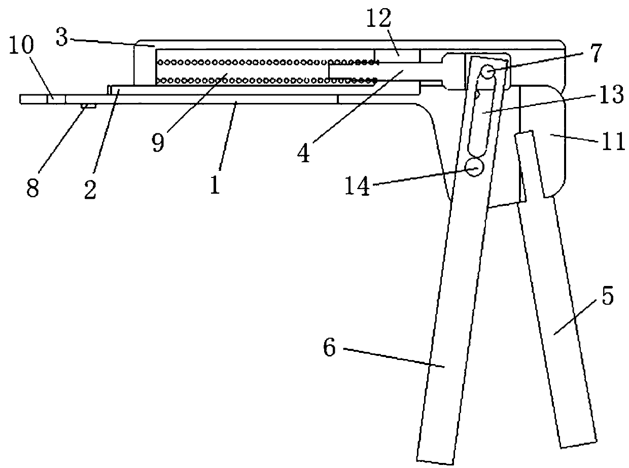
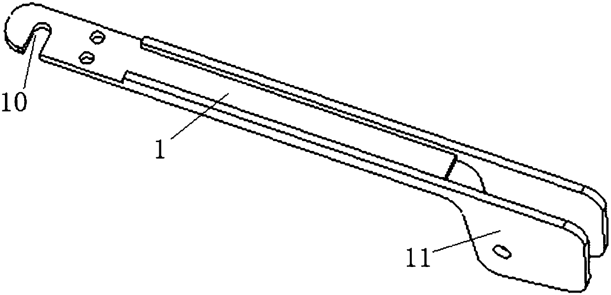
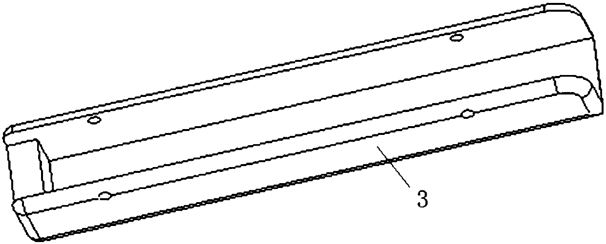
[0017] Such as Figure 1~4 As shown, the present invention includes a slideway 1, a push rod 2, a push rod cover 3, an auxiliary rod 4, a handle 5, a swing rod 6, a pin 7, a magnet 8 and a return spring 9. A U-shaped installation groove 10 for positioning the shaft part 20 is provided at the front end of the slideway 1, a magnet 8 is installed on the slideway 1 positioned behind the U-shaped installation groove 10, and a connection is integrally provided at the rear end of the slideway 1. plate 11. The push rod 2 is slidably arranged on the slideway 1 , and a stopper 12 is arranged at the rear end of the push rod 2 . The push rod cover 3 is buckled and installed on the slideway 1, and the front end of the push rod cover 3 is provided with a gap for the front end of the push rod 2 to pass through. The auxiliary rod 4 is fixedly connected with the bl...


PUM


Abstract

The invention relates to a split washer mounting tool which comprises a slideway, a push rod, a push rod cover, an auxiliary rod, a handle, a swing rod, a pin, a magnet and a resetting spring. A U-shaped mounting groove for positioning a shaft part is formed in the front end of the slideway, the magnet is mounted on the slideway positioned in rear of the U-shaped mounting groove, and a connectingplate is integrally arranged at the rear end of the slideway; the push rod is slidably arranged on the slideway, a retaining block is arranged at the rear end of the push rod, the push rod cover is mounted on the slideway in a fastened manner, and a notch for the front end of the push rod to penetrate out is arranged at the front end of the push rod cover; the auxiliary rod is fixedly connected with the retaining block, the pin is mounted at the rear end of the auxiliary rod, the handle is fixedly connected with the connecting plate, the swing rod is positioned in front of the handle, the middle of the swing rod is rotatably connected with the connecting plate while the upper end of the same is provided with a kidney-shaped hole, and the pin is positioned in the kidney-shaped hole; the resetting spring is mounted in a cavity formed by the push rod cover and the slideway, and one end of the resetting spring is abutted against the front end of the push rod cover while the other end of the same is abutted against the retaining block.

Description

technical field [0001] The invention relates to a snap ring installation tool for installing a snap ring (especially an E-type snap ring) with a shaft component. Background technique [0002] During the assembly process of electric tools or small household appliances, some shaft parts (such as pin shafts, wheel shafts, connecting pins, etc.) are usually fixed by retaining rings. On the one hand, it limits the position of the parts, and on the other hand, it plays the role of clamping. At present, open-end pliers are generally used to install the retaining ring and shaft components. During the installation process, the retaining ring is not easy to reach the predetermined position at one time, and the operation is laborious for workers, and the appearance of the parts is easy to be damaged. It can be seen that the existing installation method is not conducive to the improvement of worker efficiency and product quality. Therefore, it is necessary to develop a special tool th...

Claims


Application Information

Patent Timeline
Patent Type & Authority Applications(China)
IPC IPC(8): B25B27/00
CPCB25B27/00
Inventor 李顺才袁冠雷陈飞喻秋梁丽李强
Owner XUZHOU NORMAL UNIVERSITY
Why Eureka
Try Eureka