A fiber grating wind speed and direction sensor

A fiber grating, wind speed and wind direction technology is applied in the direction of instruments, fluid velocity measurement, optical devices, etc. It can solve the problems of not considering the temperature on the measurement equipment, the damage accuracy of components, and the low accuracy, so as to reduce the loss of components. The effect of small collision effect and increased service life

Active Publication Date: 2021-08-10
SHIJIAZHUANG TIEDAO UNIV
View PDF6 Cites 0 Cited by
  • Summary
  • Abstract
  • Description
  • Claims
  • Application Information

AI Technical Summary

Problems solved by technology

This method relies on the mutual collision between the parts, which will lead to damage to the parts and inaccurate accuracy after long-term use, and does not take into account the influence of temperature on the measuring equipment, so the accuracy is not high

Method used


Image

  • A fiber grating wind speed and direction sensor
  • A fiber grating wind speed and direction sensor
  • A fiber grating wind speed and direction sensor

Examples


Embodiment Construction

[0025] In order to make the purpose, technical solutions and advantages of the present application, the embodiments of the present application will be described in detail below with reference to the accompanying drawings. It should be noted that the features in the embodiments and embodiments in the present application may be any combination with each other in the case of an unable conflict.

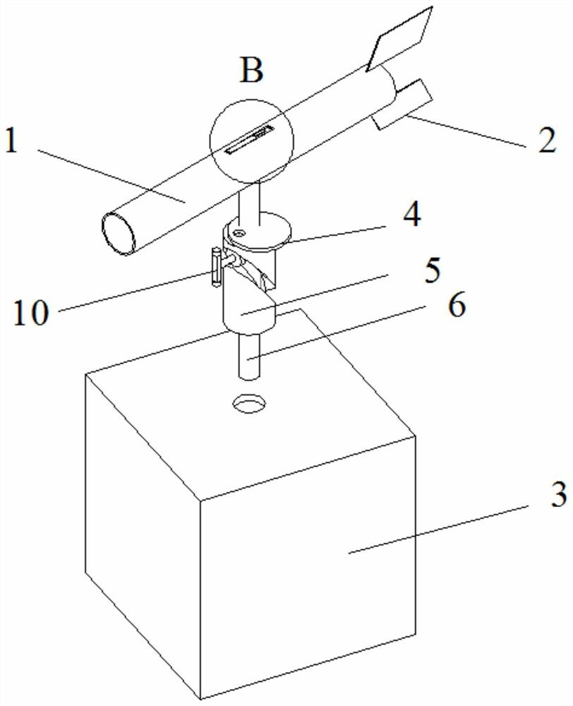
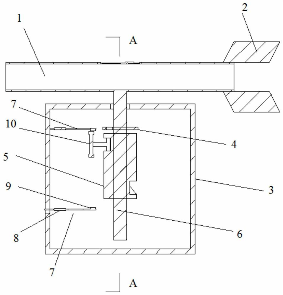
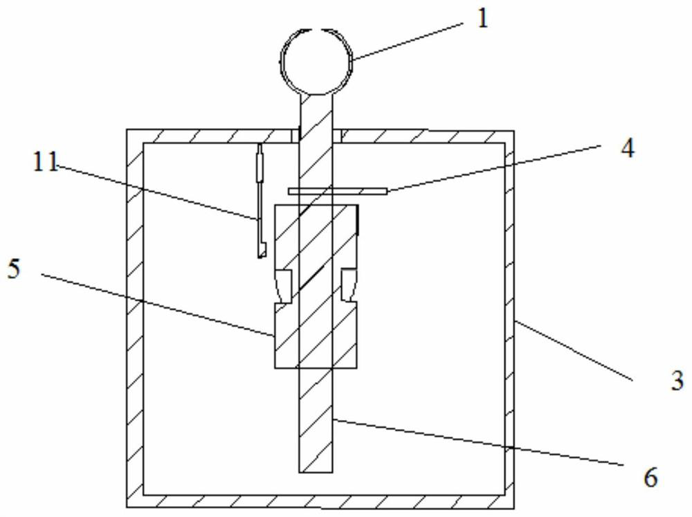
[0026] like figure 1 and 2 As shown, it shows a schematic structural diagram of the fiber grating wind speed wind direction sensor according to the present application. The fiber-optic grating wind speed wind soil sensor of the present application includes a thin-walled cylinder 1 and a package 3, and a thin-walled cylinder 1 is connected to the shaft 6 and is disposed above the package 3. Preferably, the rotating shaft 6 can be secured to the mounting hole above the package 3 by a bearing. The two ends of the thin-walled cylinder 1 are opened at one end thereof 2. The thin-walled cylinders ...


PUM


Abstract

This application relates to a fiber grating wind speed and direction sensor, including a thin-walled cylinder and a package body. The upper middle part of the thin-walled cylinder is hollowed out, and a third equal-strength cantilever beam is installed in this area. The central axis of the upper and lower surfaces of the third equal-strength cantilever beam The fiber grating sensors are symmetrically pasted on the top respectively; it also includes a direction cam, a cylindrical cam and a push rod arranged in the package body, and a horizontal equal-strength cantilever beam is respectively connected to the upper and lower parts of the inner side of the package body, and is hung and installed on the top side of the package body A vertical equal-intensity cantilever beam, fiber grating sensors are pasted on both sides of the equal-intensity cantilever beam, and a permanent magnet is provided at the free end to sense the magnetic force change of the permanent magnet on the equal-intensity cantilever beam. The application has a light structure and is not easy to be damaged, and realizes real-time online monitoring of wind speed and direction by utilizing the physical properties of fiber gratings such as small size, anti-electromagnetic interference, good electrical insulation performance and large transportation capacity.

Description

Technical field [0001] The present application relates to a fiber-optic raster wind speed winding sensor, which is suitable for the technical field of wind speed wind direction detection. Background technique [0002] The wind speed wind direction measurement technology application is very wide: in the field of agriculture, the wind speed has an important impact on the harvest of farmland; in the field of meteorological, accurate wind direction change data for marine meteorological warning systems, wind speed wind is predicting typhoon coverage and "operation" "One of the important parameters of the trajectory; in the field of clean energy, the state attaches great importance to wind energy development and utilization. Currently used wind speed windsome measuring means: capacitive force sensor, ultrasonic force sensor, dielectric force sensor. The above sensor requires active power supply, and the sensing signal is easily electromagnetic interference during transmission. [0003]...

Claims


Application Information

Patent Timeline
Patent Type & Authority Patents(China)
IPC IPC(8): G01P5/06G01P13/02G01B11/16
CPCG01B11/165G01P5/06G01P13/02
Inventor 张浩钟志鑫段君淼刘广逊王麒麟郑志超李晓瑾刘颖郭志利翟步升张雷刘辛宇
Owner SHIJIAZHUANG TIEDAO UNIV
Why Eureka
Try Eureka