Plastic flexible tube for air exhausting equipment

A technology of plastic hose and air extraction equipment, which is applied in the direction of suction hose, hose, mechanical equipment, etc., can solve the problems of limited flexibility and achieve the effect of flexibility

Active Publication Date: 2018-02-13
法兰克工业管道有限两合公司
View PDF6 Cites 5 Cited by
  • Summary
  • Abstract
  • Description
  • Claims
  • Application Information

AI Technical Summary

Problems solved by technology

[0003] However, the vacuum cleaner hose known from US 1892382A has the disadvantage of limited flexibility

Method used


Image

  • Plastic flexible tube for air exhausting equipment
  • Plastic flexible tube for air exhausting equipment
  • Plastic flexible tube for air exhausting equipment

Examples


Embodiment Construction

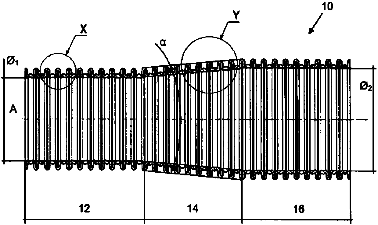
[0026] figure 1 An example of a plastic hose 10 according to the invention is shown, which in this case is part of a vacuum cleaner hose according to the invention, in particular part of an endless hose eg leaving an extrusion device. The endless hose is then divided into individual hose sections having predetermined lengths as required.

[0027] figure 1 The shown vacuum cleaner hose 10 comprises a constant inner diameter Φ 1 A first cylindrical longitudinal section 12, a second cylindrical longitudinal section 14 with a variable inner diameter and a constant inner diameter Φ 2 The third cylindrical longitudinal section 16, wherein the inner diameter Φ of the third longitudinal section 16 2 greater than the inner diameter Φ of the first longitudinal section 12 1 . The inner diameter of the second longitudinal section 14 gradually increases in the extension from the longitudinal section 12 to the longitudinal section 16 , that is, the second longitudinal section 14 is on ...


PUM


Abstract

The invention relates to a plastic flexible tube (10) for air exhausting equipment, particularly a vacuum cleaner plastic flexible tube (10). The plastic flexible tube is provided with at least one longitudinal section (14) in a longituidinal extending direction. The inner diameter of the plastic flexible tube (10) is variable in the longitudinal section. The plastic flexible tube is characterizedin that the plastic flexible tube forms a squeezed corrugated tube (18); the corrugated tube is provided with a radially outer peak (20), a radially inner valley (22) and a side section (24) which correspondingly extends between the peak (20) and the valley (22), wherein each valley (22) which is arranged in at least one longitudinal section (14) comprises an appropriately planar section (26) which faces the inner part of the plastic flexible tube (10). Furthermore the invention relates to application of the plastic flexible tube (10) according to the invention.

Description

technical field [0001] The invention relates to a plastic hose for an extraction device, in particular a plastic hose for vacuum cleaners, which plastic hose has at least one longitudinal section along its longitudinal extension, the inner diameter of the plastic hose being at the longitudinal section variable. Background technique [0002] US 1892382A discloses a vacuum cleaner hose of this type manufactured according to the coiling method. It was already known in the 1930s that a higher suction capacity can be achieved at the vacuum cleaner nozzle by means of an enlarged vacuum cleaner hose from the vacuum cleaner nozzle to the vacuum cleaner unit, with the electrical power consumption of the vacuum cleaner unit remaining the same , because in this case the flow velocity of the sucked-in air is greater at the vacuum cleaner nozzle than at the vacuum cleaner unit. [0003] However, the vacuum cleaner hose known from US 1892382A has the disadvantage of limited flexibility....

Claims


Application Information

Patent Timeline
Patent Type & Authority Applications(China)
IPC IPC(8): F16L11/15A47L9/24
CPCA47L9/24F16L11/15F16L11/111
Inventor R·维林格
Owner 法兰克工业管道有限两合公司
Why Eureka
Try Eureka