Industrial personal computer which is convenient to clean and cool

An industrial computer and cooling fan technology, which is applied in the sequence/logic controller program control, electrical program control, cooling/ventilation/heating transformation and other directions, can solve the problems of industrial computer cleaning and inconvenient heat dissipation, and achieves simple structure, Low cost and the effect of improving work efficiency

Inactive Publication Date: 2018-02-13
合肥市施能电子科技有限公司
10 Cites 2 Cited by

AI-Extracted Technical Summary

Problems solved by technology

[0004] The purpose of the present invention is to provide an industrial computer that is easy to clean and dissipate heat, so as to solve ...

Method used

Principle of work of the present invention and use process: after the present invention is installed, turn on power switch, the motor 3 in cooling fan 4 and exhaust fan 9 rotates, and fan blade 2 is arranged on motor 3 rotating shafts, thus fan blade 2 rotates , the exhaust fan 9 draws the cool air from the outside to the inside of the body 1, and the cooling fan 4 on the other side rotates, blowing the hot gas in the body 1 out of the body 1, because the exhaust fan 9 draws the air from the outside. Into the cold air, the cooling fan 4 discharges the gas in the body 1, thus forming a cycle, so that the air in the body 1 is in a circulating state, which is conducive to the normal operation of the components in the body 1, and the mounting plate 7 is installed on the body 1...

Abstract

The invention discloses an industrial personal computer which is convenient to clean and cool. The industrial personal computer comprises a computer body, dustproof mechanisms and gasket supports, a cooling groove is formed in the bottom surface inside the computer body, cooling fans are arranged at the upper end and the lower end of the surface of one side inside the computer body, exhaust fans are arranged at the upper end and the lower end of the surface of the other side inside the computer body, and mounting grooves are formed in the middles of the surfaces of the two sides inside the computer body. The industrial personal computer has the advantages that the cooling fans are installed at one side of the computer body, the exhaust fans are installed at the other side of the computer body, so that air inside the computer body is in a circulation state all the time, hot airflow generated by cooling of components and parts is exhausted out of the computer body together with cold airflow through the cooling fans, and it is guaranteed that the temperature inside the computer body is balanced; the dustproof mechanisms are arranged at the two sides of the computer body, and dustproofnets of the dustproof mechanisms are of detachable structures; meanwhile, cooling sheets on the upper surface of the computer body are also detachable, and the industrial personal computer is convenient to clean.

Application Domain

Programme control in sequence/logic controllersCooling/ventilation/heating modifications

Technology Topic

Heat sinkAirflow +4

Image

  • Industrial personal computer which is convenient to clean and cool
  • Industrial personal computer which is convenient to clean and cool

Examples

  • Experimental program(1)

Example Embodiment

[0018] The technical solutions in the embodiments of the present invention will be clearly and completely described below in conjunction with the accompanying drawings in the embodiments of the present invention. Obviously, the described embodiments are only a part of the embodiments of the present invention, rather than all the embodiments. Based on the embodiments of the present invention, all other embodiments obtained by those of ordinary skill in the art without creative work shall fall within the protection scope of the present invention.
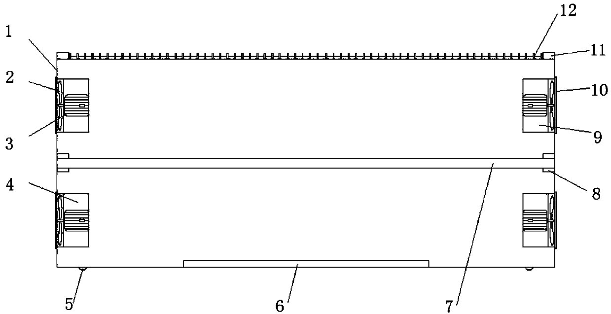
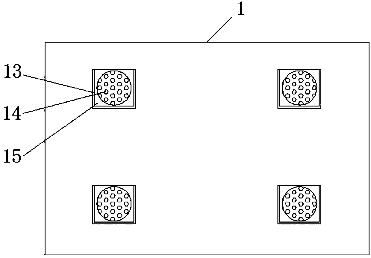
[0019] See Figure 1-2 , The present invention provides a technical solution:
[0020] An industrial computer that is easy to clean and easy to dissipate, including a body 1, a dust-proof mechanism 10 and a gasket bracket 15. The bottom surface of the body 1 is provided with a heat dissipation groove 6, and the upper and lower ends of the inner surface of the body 1 The heat dissipation fan 4 is provided, the upper and lower ends of the other side surface of the inside of the body 1 are provided with exhaust fans 9, the middle of the inner two surfaces of the body 1 is provided with a mounting groove 8, and the middle of the body 1 is provided with a mounting plate 7. The two ends of the mounting plate 7 are embedded and installed in the inside of the mounting groove 8. The upper surface of the body 1 is provided with radiating fins 12, both ends of the upper surface of the body 1 are provided with storage slots 11, and there are eight dust-proof mechanisms 10, In addition, eight dust-proof mechanisms 10 are respectively installed on both sides of the body 1 at positions corresponding to the wind blades 2, and rubber pads 5 are provided on the bottom surface of the body 1.
[0021] In order to quickly dissipate heat, in the present invention, preferably, a motor 3 is arranged inside the heat dissipating fan 4 and the exhaust fan 9. The rotating shaft of the motor 3 is close to the inner side of the body 1, and the rotating shaft of the motor 3 is provided with fan blades 2, 3 and the outside. The power supply is electrically connected.
[0022] In order to facilitate cleaning and dust prevention, in the present invention, it is preferable that the two sides and bottom surface of the dust-proof mechanism 10 are provided with clamping grooves 13, the gasket bracket 15 is embedded and installed in the clamping groove 13, and the gasket bracket 15 is close to a side of the body 1. A dust-proof net 14 is provided on the side surface.
[0023] In order to dissipate heat and prevent dust, in the present invention, preferably, a dust-proof net 14 is provided around the heat dissipation groove 6.
[0024] In order to facilitate disassembly, in the present invention, preferably, one end of the heat sink 12 is embedded and installed on the surface of the body 1.
[0025] In order to increase the effective heat dissipation area, in the present invention, preferably, a through hole is provided on the surface of the spacer bracket 15.
[0026] The working principle and use process of the present invention: After the present invention is installed, the power switch is turned on, the motor 3 in the cooling fan 4 and the exhaust fan 9 rotates, and the fan 2 is arranged on the rotating shaft of the motor 3, so the fan 2 rotates and the exhaust fan 9 The cool air from the outside is pumped into the body 1, while the cooling fan 4 on the other side rotates, and the hot air in the body 1 is blown out of the body 1. As the exhaust fan 9 draws the cold air from the outside The heat dissipation fan 4 exhausts the air in the body 1, thus forming a cycle, so that the air in the body 1 is in a circulating state, which is beneficial to the normal operation of the components in the body 1. The mounting plate 7 is installed in the middle of the body 1. , Fixed by the installation slot 8, so that the components are installed in the middle position, which increases the heat dissipation area. At the same time, the upper surface of the body 1 is provided with storage slots 11 at both ends. The storage slots 11 are placed with heat sinks 12, and the heat sinks 12 pass through the body 1 Surface grooves are installed on the upper surface of the body 1, which is easy to disassemble and dissipate heat. Dust-proof mechanisms 10 are detachable on both sides to facilitate dust removal. The traditional heat sinks 12 are fixed, which is very inconvenient to clean. Disassembling the heat sink 12 can easily clean up the stolen goods on the surface of the body 1 and is convenient and safe to use.
[0027] Although the embodiments of the present invention have been shown and described, those of ordinary skill in the art can understand that various changes, modifications, and substitutions can be made to these embodiments without departing from the principle and spirit of the present invention. And variations, the scope of the present invention is defined by the appended claims and their equivalents.

PUM

no PUM

Description & Claims & Application Information

We can also present the details of the Description, Claims and Application information to help users get a comprehensive understanding of the technical details of the patent, such as background art, summary of invention, brief description of drawings, description of embodiments, and other original content. On the other hand, users can also determine the specific scope of protection of the technology through the list of claims; as well as understand the changes in the life cycle of the technology with the presentation of the patent timeline. Login to view more.

Similar technology patents

Large size mounting RFID upside-down mounting pasting method and apparatus thereof

InactiveCN102324393AImprove work efficiencysave sample time
Owner:广东宝丽华服装有限公司

Device for removing low-melting-point alloy from inner cavity of blade

ActiveCN106761953Ashort removal timeImprove work efficiency
Owner:CHINA HANGFA SOUTH IND CO LTD

Classification and recommendation of technical efficacy words

  • Simple structure
  • Improve work efficiency

Sharing system for air-conditioning coat

InactiveCN107440179ASimple structureeasy to wear
Owner:QINGDAO HAIER AIR CONDITIONER GENERAL CORP LTD

Emergency parachuting device and method for multiple-rotor unmanned aerial vehicle

InactiveCN103895870Aavoid aircraft crashSimple structure
Owner:SOUTH CHINA AGRI UNIV +1

Quick pipe connector

Owner:YANG RICHARD

Automatic washing and dewatering combined device of rotary type mop

InactiveCN102370447Areduce volumeSimple structure
Owner:上海祥美网络科技有限公司 +1

Cooperation service platform facing different source data

InactiveCN101174957AImprove management level and qualityImprove work efficiency
Owner:NANJING UNIV OF FINANCE & ECONOMICS

Screw drilling tool, vertical drilling tool testing method and well inclination simulation testing equipment

InactiveCN111594144AReduced height requirementsImprove work efficiency
Owner:DEZHOU UNITED GASOLINEEUM MACHINERY

Method for intelligent automatic identification of transmission circuit parts

Owner:INFORMATION COMM COMPANY STATE GRID SHANDONG ELECTRIC POWER +2

Keyboard spill-proofing mechanism

ActiveUS7030330B2minimize manufacturing costimprove work efficiency
Owner:LITE ON SINGAPORE PTE LTD
Why Eureka
Try Eureka