
Positioning device for fetal heart monitor

A positioning device and monitor technology, applied in pulse/heart rate measurement, medical science, sensors, etc., can solve the problems of easy falling off, not environmental protection, and inability to find the position of the fetal heart, and achieve the effect of firm comfort

Inactive Publication Date: 2018-02-16
孙培培
View PDF7 Cites 0 Cited by
  • Summary
  • Abstract
  • Description
  • Claims
  • Application Information

AI Technical Summary

Problems solved by technology

[0003] (1) When using a fetal heart rate monitor, it is very important to find the position of the fetal heart rate correctly, and the position of the fetal heart rate varies with the change of pregnancy. In the past, fetal heart rate monitoring relied on the experience of doctors to find the best position. Position, under the current trend that home fetal heart monitors are entering more and more families, many mothers complain that they are always unable to find the position of the fetal heart rate, which affects the use and sometimes delays the timely monitoring of the fetus;
[0004] (2) The positioning device of the fetal heart rate monitor currently in use is mostly bound to the abdomen of the pregnant woman with an elastic band, or is pasted on the abdomen of the pregnant mother with a one-time adhesive tape. The way is not comfortable, it will leave glue on the pregnant mother's abdomen, and it is not environmentally friendly;
[0005] (3) It is very inconvenient and inefficient to adjust the position of the probe after the probe is fixed on the abdomen of the pregnant mother in the current positioning device of the fetal heart rate monitor.

Method used


Image

  • Positioning device for fetal heart monitor
  • Positioning device for fetal heart monitor
  • Positioning device for fetal heart monitor

Examples


Embodiment

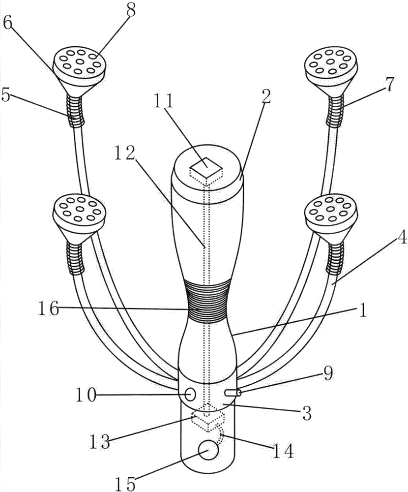
[0025] Such as figure 1 As shown, the present invention provides a positioning device for a fetal heart rate monitor, including a probe rod 1, which is dumbbell-shaped, and an anti-slip thread 16 is provided on the outer surface of the middle depression of the probe rod 1, and has It is beneficial for pregnant women to hold the probe rod 1 for fixing, the top of the probe rod 1 is provided with a probe 2, the bottom of the probe rod 1 is provided with a negative pressure evacuating machine 3, and the negative pressure evacuating machine 3 is fixedly connected with four fixing frames 4 , the other ends of the four fixing frames 4 are connected to the suction head 6 through the telescopic tube 5 .

[0026] Such as figure 1 As shown, the interior of the fixed frame 4 is a hollow structure, and a negative pressure channel is formed inside the fixed frame 4 to directly communicate with the negative pressure evacuator 3 to maintain the negative pressure of the suction head 6. The t...


PUM

PropertyMeasurementUnit
Diameteraaaaaaaaaa

Abstract

The invention discloses a positioning device for a fetal heart monitor. The device includes a probe rod, and the top of the probe rod is provided with a probe; the bottom of the probe rod is providedwith a negative pressure vacuator, and the negative pressure vacuator is fixedly connected with four fixing supports; the fixing supports are connected with adsorption heads through extension tubes, each extension tube is internally provided with a flexible metal hose, and the surface of each adsorption head is provided with adsorption holes; the negative pressure vacuator is fixedly provided withan exhaust pipe, the side surface of the negative pressure vacuator is provided with a switch, and the interior of the probe is fixedly provided with a vibration sensor; the vibration sensor is connected with an ARM single chip microcomputer through a signal cable, and the ARM single chip microcomputer is connected with a buzzer through a control wire. By arranging the vibration sensor and the buzzer, the position of a fetal heart is looked for more effectively and accurately for a pregnant woman, and by arranging the adsorption heads and the negative pressure vacuator, air pressure is used for fixing the probe which is firm and good in comfort level; the negative pressure vacuator is provided with the switch, so that the probe is convenient to fix and take down.

Description

technical field [0001] The invention relates to the technical field of fetal heart rate monitoring, in particular to a positioning device for a fetal heart rate monitoring instrument. Background technique [0002] The fetal heart rate is the heartbeat of the fetus. The fetal heart rate monitoring examination uses the principle of ultrasound to monitor the situation of the fetus in the uterus. It is the main detection method to correctly evaluate the condition of the fetus in the uterus. The curve of the monitoring graph formed by the signal tracing instantaneous fetal heart rate change can understand the reaction of the fetal heart rate during fetal movement and uterine contraction. The positioning device of the currently used fetal heart rate monitor has the following shortcomings: [0003] (1) When using a fetal heart rate monitor, it is very important to find the position of the fetal heart rate correctly, and the position of the fetal heart rate varies with the change of...

Claims


Application Information

Patent Timeline
IPC IPC(8): A61B5/024A61B5/00
CPCA61B5/02411A61B5/02444A61B5/4362A61B5/7405A61B5/7455
Inventor 孙培培
Owner 孙培培
Learn More