Femoral condyle prosthesis and artificial knee joint

A femoral condyle and prosthesis technology, applied in the direction of knee joints, elbow joints, joint implants, etc., can solve the problems of wear and tear on the contact parts between columns and cams, and achieve the effect of reducing wear and improving service life

Pending Publication Date: 2018-02-16
北京安颂科技有限公司
View PDF0 Cites 0 Cited by
  • Summary
  • Abstract
  • Description
  • Claims
  • Application Information

AI Technical Summary

Problems solved by technology

[0007] The purpose of the present invention is to provide a femoral condyle prosthesis to solve the technical problem of severe wear of the contact parts of the column and the cam in the prior art
[0008] The purpose of the present invention is also to provide an artificial knee joint to solve the technical problem of severe wear of the contact parts of the column and the cam in the prior art

Method used


Image

  • Femoral condyle prosthesis and artificial knee joint
  • Femoral condyle prosthesis and artificial knee joint
  • Femoral condyle prosthesis and artificial knee joint

Examples


Embodiment 1

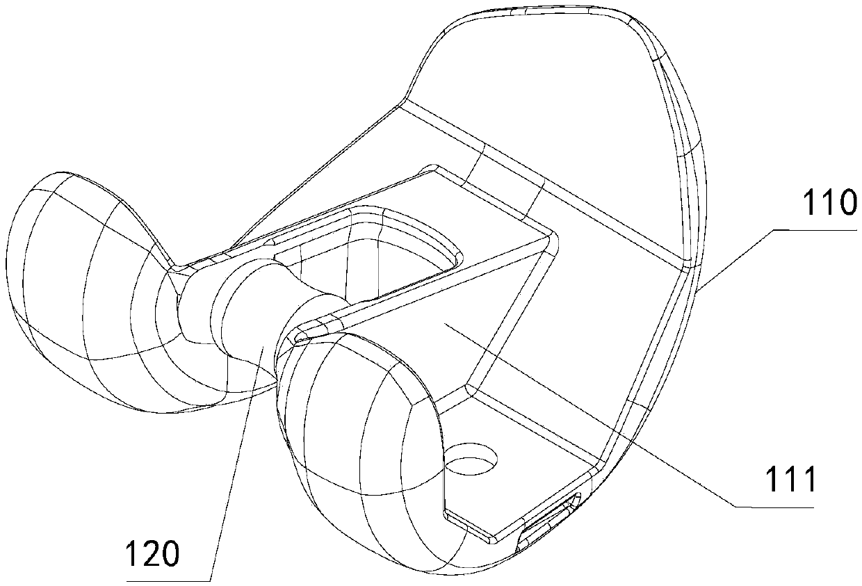
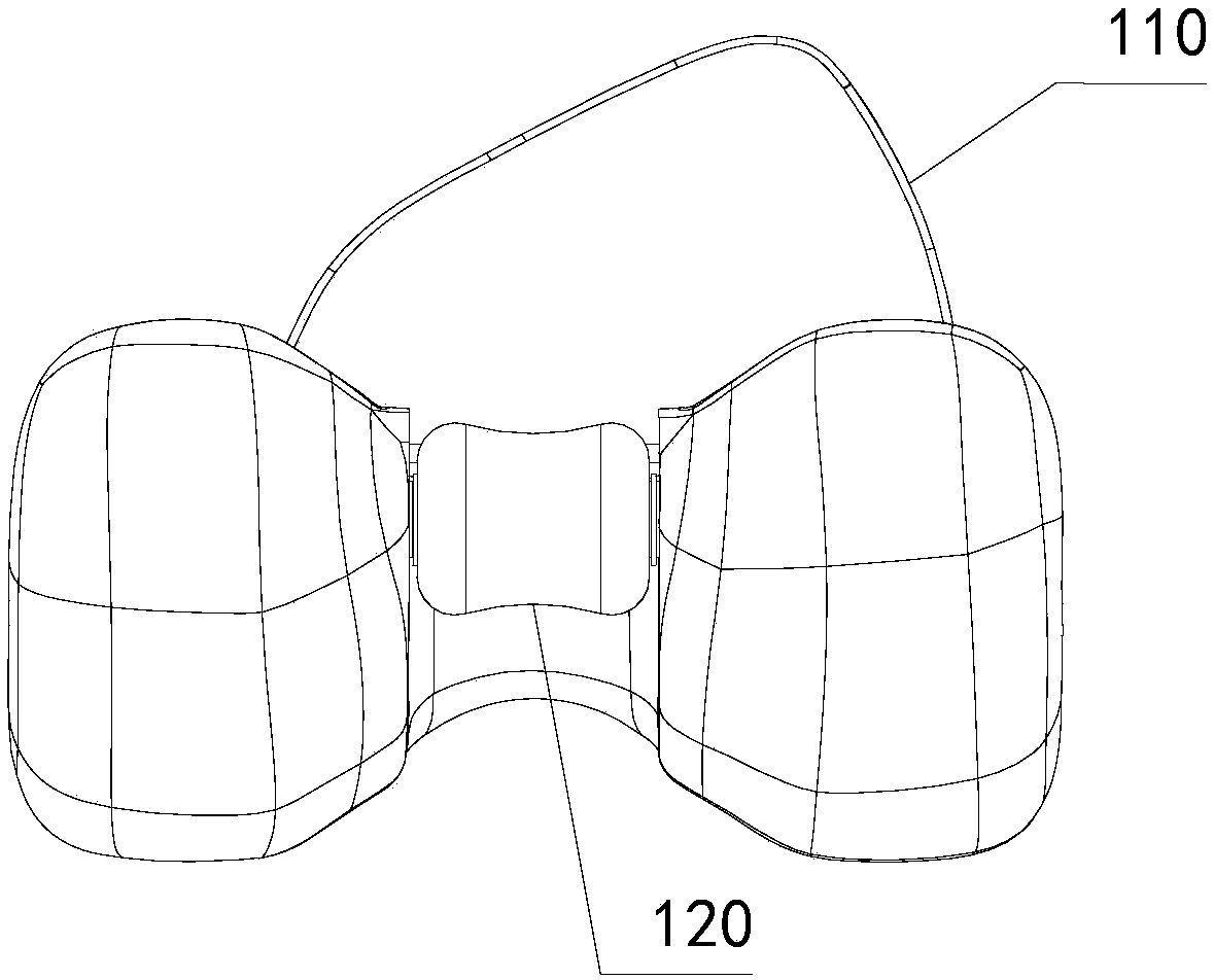
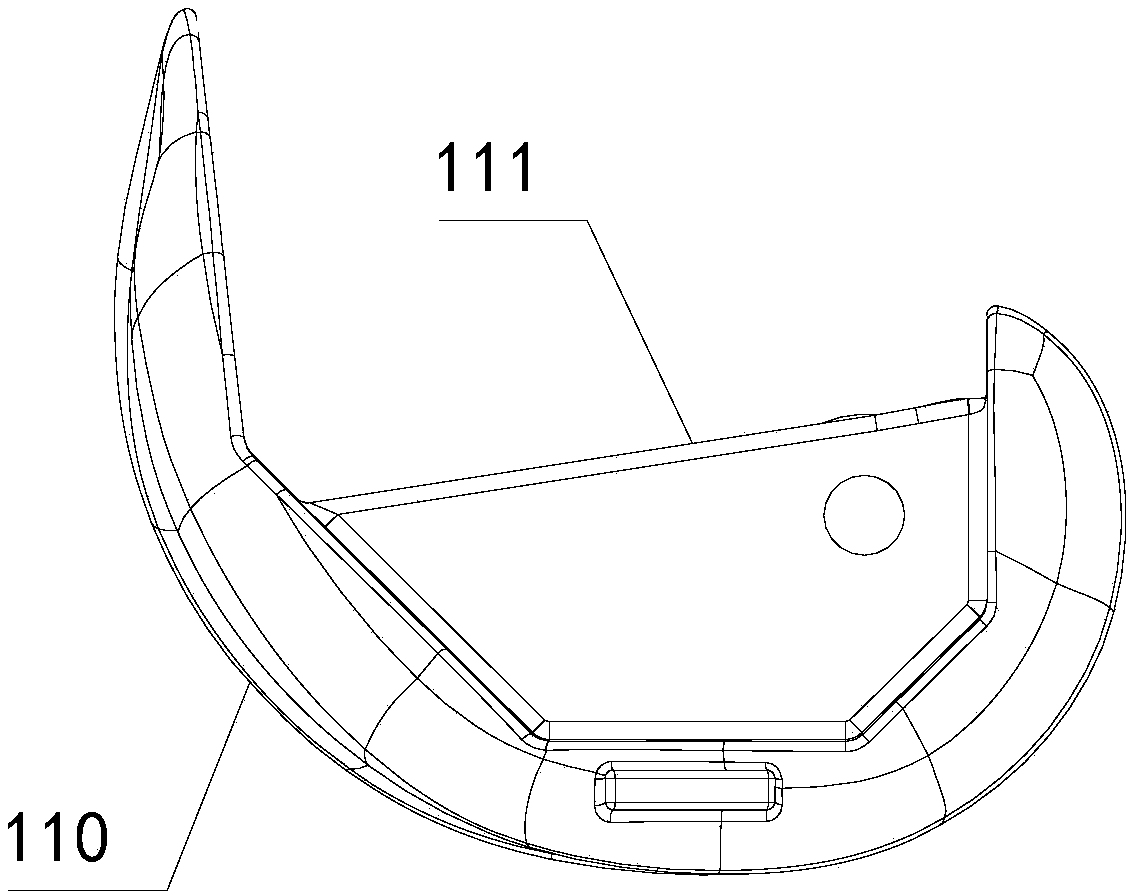
[0054] see Figure 1-Figure 9 Shown, the present embodiment provides a kind of femoral condyle prosthesis; figure 1 The perspective view of the femoral condyle prosthesis provided for this embodiment; figure 2The front view of the femoral condyle prosthesis provided for this embodiment; image 3 for figure 2 Left view of the femoral condyle prosthesis shown; Figure 4 for figure 2 A top view of the femoral condyle prosthesis shown; Figure 5 Exploded schematic diagram of the femoral condyle prosthesis provided for this embodiment; in order to show the structure of the cam and the connector more clearly, Image 6 is the exploded schematic diagram of the cam and the connector; Figure 7-Figure 9 is the structural schematic diagram of the cam, where, Figure 7 The cam shown is a rotary body, Figure 8 , Figure 9 Cams shown are non-rotating.

[0055] see Figure 1-Figure 9 As shown, the femoral condyle prosthesis provided in this embodiment is applied to an artifici...


PUM

PropertyMeasurementUnit
Gapaaaaaaaaaa

Abstract

The invention relates to the technical field of medical apparatuses and instruments, in particular to a femoral condyle prosthesis and an artificial knee joint. The femoral condyle prosthesis comprises a femoral condyle basis body and a cam; the cam is arranged in an intercondylar box of the femoral condyle basis body, and is rotationally connected with the intercondylar box. The artificial knee joint comprises the femoral condyle prosthesis. The femoral condyle prosthesis and the artificial knee joint aim at solving the technical problem that in the prior art, the contact part between a standing column and the cam is seriously worn.

Description

technical field [0001] The invention relates to the technical field of medical devices, in particular to a femoral condyle prosthesis and an artificial knee joint. Background technique [0002] The artificial knee prosthesis is implanted into the human body after knee replacement, and its function is to restore the normal physiological functions of the human body. In knee replacement surgery, if the patient's lesions are severe and the posterior cruciate ligament cannot be preserved, it needs to be resected during the operation. For patients who have had the posterior cruciate ligament resected, only a posterior-stabilized prosthesis (ie, PS-type prosthesis) can be used for surgery. [0003] For the posterior stabilized knee prosthesis, since the posterior cruciate ligament is resected during the operation, a column-cam mechanism (ie, POST-CAM mechanism) is set in the artificial knee joint to simulate and replace the function of the posterior cruciate ligament. The posteri...

Claims


Application Information

Patent Timeline
IPC IPC(8): A61F2/38
CPCA61F2/3836A61F2/3859
Inventor 贾海涛
Owner 北京安颂科技有限公司
Why Eureka
Try Eureka