A high-frequency induction welding method for battery terminals

A technology of high-frequency induction welding and terminal blocks, which is applied in the direction of high-frequency current welding equipment, welding equipment, metal processing equipment, etc., can solve the problems of high product failure rate, prolong working time, and potential safety hazards, and improve the welding efficiency. quality, improve positioning efficiency, and facilitate the effect of automatic reset

Active Publication Date: 2018-08-17
浙江金麦特自动化系统有限公司
View PDF7 Cites 0 Cited by
  • Summary
  • Abstract
  • Description
  • Claims
  • Application Information

AI Technical Summary

Problems solved by technology

[0002] Recently, in the field of battery processing, the terminal is fixedly connected to the positive and negative poles on the battery by welding. The traditional method is to weld the terminal with a welding torch combined with a welding wire. This welding method has a complex structure and cumbersome operation. , low efficiency and poor welding quality, high product failure rate
[0003] In addition, the lugs after welding by the above method are uneven and prone to bulges, which need to be cut and removed manually to avoid short circuits, but the welding process is increased, the working time is prolonged, and the work efficiency is reduced. There are safety hazards in the process

Method used


Image

  • A high-frequency induction welding method for battery terminals
  • A high-frequency induction welding method for battery terminals
  • A high-frequency induction welding method for battery terminals

Examples


Embodiment 1

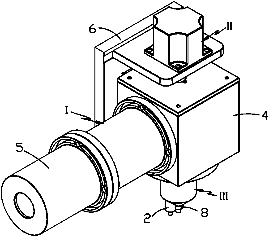
[0041] Refer to the attached Figure 1 to Figure 6 A high-frequency welding induction welding gun according to Embodiment 1 of the present invention is described.

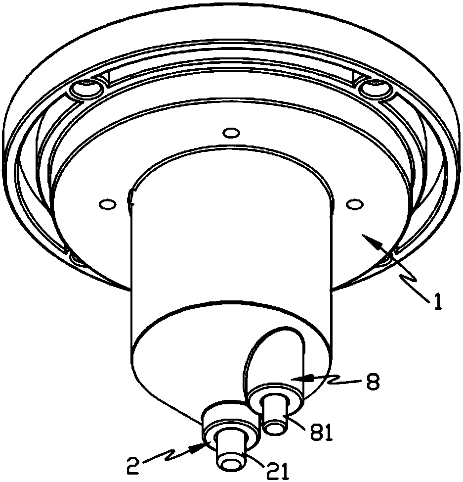
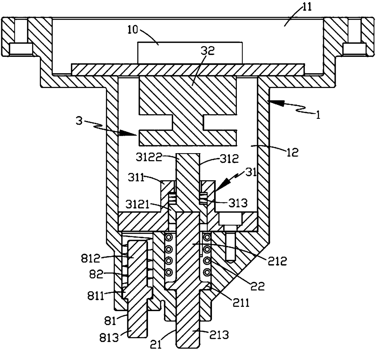
[0042] Such as figure 1 As shown, a high-frequency welding induction welding torch disclosed by the present invention includes a torch body I, a driving mechanism II that drives the torch body I to move up and down, and a torch head III, such as figure 2 with image 3 As shown, the pipette tip III includes:

[0043] Gun tip seat 1, the inside of the gun tip seat 1 is hollow;

[0044] Welding assembly 2, described welding assembly 2 is installed on the front end of described gun head seat 1, and it comprises the magnetic conduction rod 21 that the front end protrudes from described gun head seat 1 and is arranged on the outside of this magnetic conduction rod 21 and an electromagnetic induction coil 22 electrically connected to the control element 10; and

[0045] The control assembly 3, the control assembly 3...

Embodiment 2

[0061] Refer to the attached Figure 7 with Figure 8 A high-frequency induction welding method for battery terminals according to Embodiment 2 of the present invention is described.

[0062] Such as Figure 7 with Figure 8 As shown, the parts that are the same as or corresponding to the first embodiment adopt the corresponding reference numerals of the first embodiment. For the sake of simplicity, only the differences from the first embodiment are described below. The second embodiment is different from that shown in Figure 1. The difference of the first embodiment is that a high-frequency induction welding method for battery terminals of the present invention includes the following working steps:

[0063] a. Pre-pressing and feeding process, the battery 7 to be welded is moved to directly below the set position of the welding torch in sequence, and the driving mechanism II drives the torch head III to move down to the front end of the magnetic rod 21 of the welding assem...

Embodiment 3

[0076] Such as Figure 1 to Figure 10 As shown, the parts that are the same as or corresponding to those in the second embodiment adopt the reference numerals corresponding to the second embodiment. For the sake of simplicity, only the differences between the second embodiment and the third embodiment are described below. figure 1 The difference of the second embodiment shown is that this embodiment also includes a preset positioning process. In the step a, the driving mechanism II drives the gun head III to move down to the position where the positioning assembly 8 and the welding assembly 2 are aligned. Lean on the battery 7; when the welding assembly 2 performs pre-press feeding, shaping and welding on the pole, the positioning assembly 8 is all against the terminal of the terminal through the elastic action of the second elastic member 82 On the one hand, the positioning efficiency is improved, and at the same time, the positioning component 8 can always press and hold the...


PUM


Abstract

The invention relates to a high-frequency induction welding method for terminals of storage batteries. The high-frequency induction welding method comprises the following working steps of a, a prepressing and feeding-in procedure is performed, namely, the to-be-welded storage batteries are moved to a position right below a set position of a welding gun in sequence, a gun head is driven by a driving mechanism to move downwards till a welding assembly abuts against one storage battery, the gun head moves downwards continually till a control unit above the welding assembly makes contact with a pressure sensor, and posts on the storage battery are heated by the welding assembly through a high-frequency electromagnetic induction heating method; b, a reshaping procedure is performed, namely, thegun head moves downwards continually, the heated and softened posts on the storage battery are pressed down synchronously by the welding assembly till the posts make contact with wiring pieces of theterminals, and the flattening of the end portions of the posts is completed; c, a welding procedure is performed, namely, after step b is completed, in the process that the gun head is driven by thedriving mechanism to move upwards to the initial position, the welding assembly breaks away from the posts, and the surface fusion welding of the posts is completed. By means of the high-frequency induction welding method for the terminals of the storage batteries, the conventional storage battery welding procedure is simplified, and the automated and continuous production of the storage batteriesis facilitated.

Description

technical field [0001] The invention belongs to the technical field of welding equipment, and in particular relates to a high-frequency induction welding method for battery terminals. Background technique [0002] Recently, in the field of battery processing, the terminal is fixedly connected to the positive and negative poles on the battery by welding. The traditional method is to weld the terminal with a welding torch combined with a welding wire. This welding method has a complex structure and cumbersome operation. , low efficiency and poor welding quality, high product failure rate. [0003] In addition, the lugs after welding by the above method are uneven and prone to bulges, which need to be cut and removed manually to avoid short circuits, but the welding process is increased, the working time is prolonged, and the work efficiency is reduced. There are safety hazards in the process. Contents of the invention [0004] The object of the present invention is to addr...

Claims


Application Information

Patent Timeline
Patent Type & Authority Patents(China)
IPC IPC(8): B23K13/01
CPCB23K13/01
Inventor 江帆徐森林江飞舟
Owner 浙江金麦特自动化系统有限公司
Why Eureka
Try Eureka