High-frequency welding induction gun head and welding gun with gun head applied

A technology for high-frequency welding and welding components, which is applied to high-frequency current welding equipment, welding equipment, metal processing equipment, etc. Can not detect and other problems, to achieve the effect of improving energy concentration and heat utilization, avoiding excessive temperature damage, and facilitating automatic reset

Active Publication Date: 2017-12-08
浙江金麦特自动化系统有限公司
View PDF9 Cites 3 Cited by
  • Summary
  • Abstract
  • Description
  • Claims
  • Application Information

AI Technical Summary

Problems solved by technology

[0005] According to the applicant’s response, although the above technical solution uses the change of the contact force between the stud and the pressure sensor to control the motion of the stud to perform precise welding, it solves the problem that the stud feeding pressure cannot be detected during the feeding process of the existing stud welding torch. The defect that the movement of the stud cannot be controlled, but there are still some problems. First of all, the welding method still uses the traditional arc welding, which needs to be used with welding wire, which is costly and difficult to operate. When welding, it is necessary to maintain a stable welding current for a period of time to form a certain molten pool to complete the welding. The temperature cannot be accurately controlled in sections, and it is impossible to locally soften, shape, and weld the battery poles. Therefore, this welding method cannot be applied to battery wiring. Soldering of terminals

Method used


Image

  • High-frequency welding induction gun head and welding gun with gun head applied
  • High-frequency welding induction gun head and welding gun with gun head applied
  • High-frequency welding induction gun head and welding gun with gun head applied

Examples


Embodiment 1

[0052] Refer to the attached Figure 1 to Figure 3 A high-frequency welding induction gun head according to Embodiment 1 of the present invention is described.

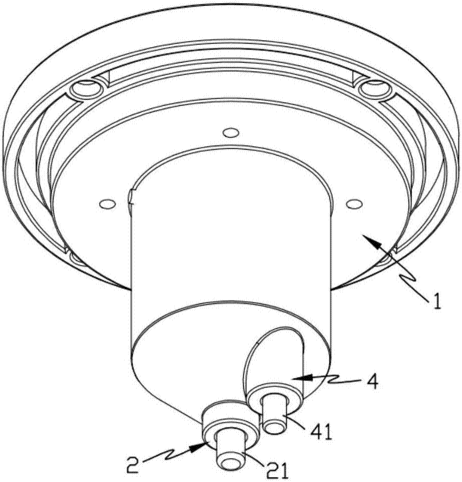
[0053] Such as figure 1 and figure 2 As shown, a high-frequency welding induction gun head, including:

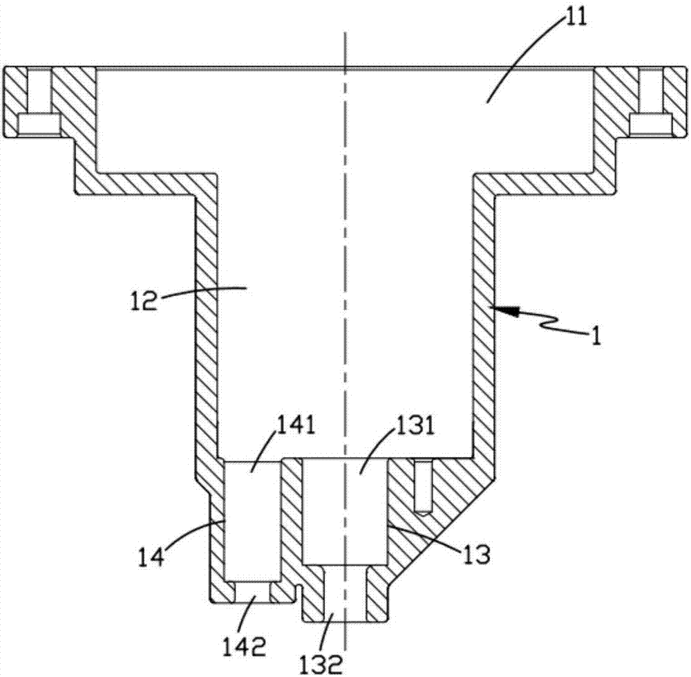
[0054] Gun tip seat 1, the inside of the gun tip seat 1 is hollow;

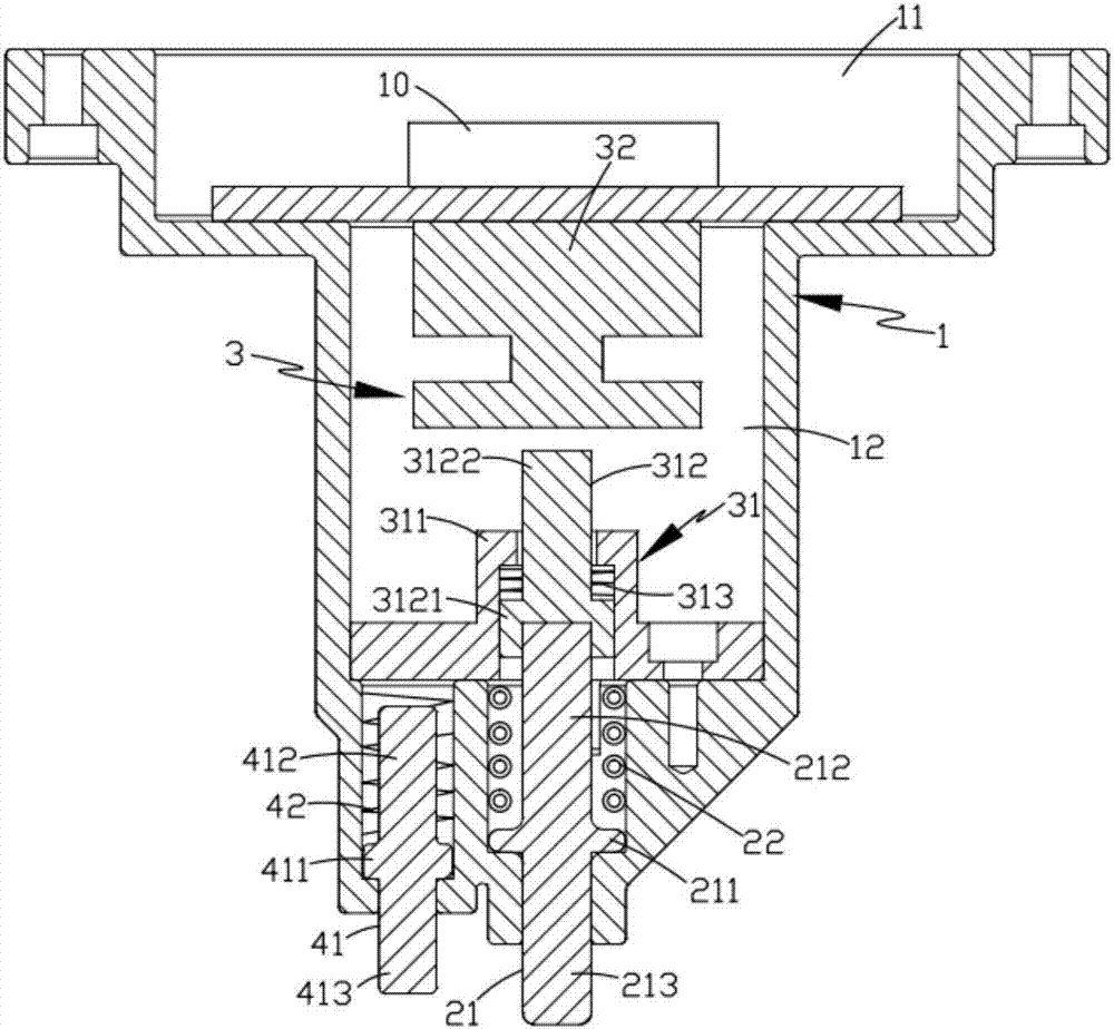
[0055] Welding assembly 2, described welding assembly 2 is installed on the front end of described gun head seat 1, and it comprises the magnetic conduction rod 21 that the front end protrudes from described gun head seat 1 and is arranged on the outside of this magnetic conduction rod 21 and a magnetic field unit 22 electrically connected to the control element 10; and

[0056] The control assembly 3, the control assembly 3 is arranged on the rear side of the welding assembly 2, it includes a control unit 31 and a pressure sensor 32 arranged on the rear side of the control unit 31 and electrically connected to the control element 10, the con...

Embodiment 2

[0067] Such as Figure 1 to Figure 5 As shown, the parts that are the same as or corresponding to the first embodiment adopt the corresponding reference numerals of the first embodiment. For the sake of simplicity, only the differences from the first embodiment are described below. The second embodiment is different from that shown in Figure 1. The difference of Embodiment 1 is: as Figure 1 to Figure 5 As shown, a high-frequency welding induction gun head of the present invention also includes a positioning assembly 4, the positioning assembly 4 is arranged on one side of the welding assembly 2, and the front end of the gun head seat 1 is also opened for cooperating with the installation. The third positioning space 14 of the positioning assembly 4, the third positioning space 14 includes a limiting hole b141 and a guiding hole b142 arranged in coaxial communication, the inner diameter of the limiting hole b141 is larger than the inner diameter of the guiding hole b142.

[0...

Embodiment 3

[0074] Such as Figure 6 and Figure 9 As shown, the parts that are the same as or corresponding to the first embodiment adopt the corresponding reference numerals of the second embodiment. For the sake of simplicity, only the differences from the second embodiment are described below. The third embodiment is similar to the second embodiment. figure 1 The difference of the second embodiment shown is that the present invention also provides a welding torch, including a torch body 5, a drive mechanism 6 that drives the torch body 5 to move up and down, and a high-frequency welding gun described in the above technical solution. Welding induction gun head, the gun body 5 includes a connection cover 51 detachably connected to the bottom of the gun head seat 1 and a sleeve 52 arranged on one side of the connection cover 51 for installing a control circuit; Figure 7 As shown, the drive mechanism 6 includes a motor 61 mounted on the frame 7, a lead screw bolt 62 and a lead screw nut...


PUM


Abstract

The invention relates to a high-frequency welding induction gun head and a welding gun with the gun head applied. The welding gun comprises a gun body, a drive mechanism and the gun head; the gun head comprises a connection cover and a casing pipe; the gun body comprises a gun head base, a welding assembly and a control assembly; the welding assembly is installed on the front end portion of the gun head base and comprises a magnetic conductive bar and an electromagnetic induction coil surrounding the magnetic conductive bar; the control assembly is arranged on the rear side of the welding assembly and comprises a control unit and a pressure sensor arranged on the rear side of the control unit; the front end of the control unit is in abutting connection with the magnetic conductive bar; and the rear end of the control unit is in non-contact connection with the pressure sensor. Shaping and fusion welding on a post terminal are completed synchronously in the welding process of a storage battery connecting terminal through cooperation of a high-frequency electromagnetic induction heating mode and lifting movement of the gun head, the traditional welding procedure is simplified, and full-automatic and mechanical welding production of the storage battery connecting terminal is easily achieved by being matched with a mechanical arm.

Description

technical field [0001] The invention belongs to the technical field of welding equipment, and in particular relates to a high-frequency welding induction gun head used for automatic welding of storage battery terminals and a welding gun using the gun head. Background technique [0002] Recently, in the field of battery processing, the terminal is fixedly connected to the positive and negative poles on the battery by welding. The traditional method is to weld the terminal with a welding torch combined with a welding wire. This welding method has a complex structure and cumbersome operation. , low efficiency and poor welding quality, high product failure rate. [0003] In addition, the lugs after welding by the above method are uneven and prone to bulges, which need to be cut and removed manually to avoid short circuits, but the welding process is increased, the working time is prolonged, and the work efficiency is reduced. There are safety hazards in the process. [0004] C...

Claims


Application Information

Patent Timeline
Patent Type & Authority Applications(China)
IPC IPC(8): B23K13/01
CPCB23K13/01B23K2101/36
Inventor 江帆陈军徐森林江飞舟
Owner 浙江金麦特自动化系统有限公司
Why Eureka
Try Eureka