
Dust reduction type steel plate double-face efficient polishing device

A steel plate and double-sided technology, which is applied in the field of high-efficiency double-sided grinding of dust-reducing steel plates, can solve the problems of inconvenient steel plate double-sided grinding operation, poor steel plate grinding effect, poor steel plate turning effect, etc., and achieve good dust removal and dust reduction effects, grinding Wide-ranging, efficiency-enhancing effects

Pending Publication Date: 2018-02-16
ZHENGZHOU UNIV
View PDF6 Cites 35 Cited by
  • Summary
  • Abstract
  • Description
  • Claims
  • Application Information

AI Technical Summary

Problems solved by technology

[0003] In the mechanical processing industry, it is necessary to polish and derust the surface of the steel plate before stamping and cutting the steel plate to make parts, so as to remove the rust stains and burrs on the surface of the steel plate and ensure the smooth surface of the steel plate. The existing steel plate grinding The grinding effect of the device on the steel plate is not good, and the grinding effect is poor. Since both sides of the steel plate need to be polished, the existing grinding device has a poor turning effect on the steel plate, which is not convenient for double-sided grinding of the steel plate.

Method used


Image

  • Dust reduction type steel plate double-face efficient polishing device
  • Dust reduction type steel plate double-face efficient polishing device
  • Dust reduction type steel plate double-face efficient polishing device

Examples


Embodiment Construction

[0019] Below in conjunction with specific embodiment, the technical scheme of this patent is described in further detail:

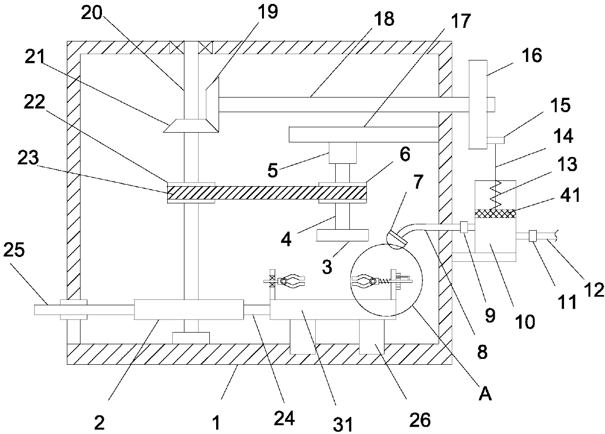
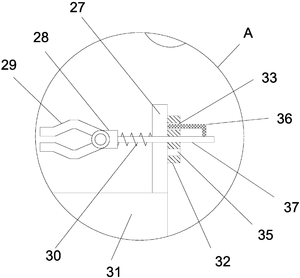
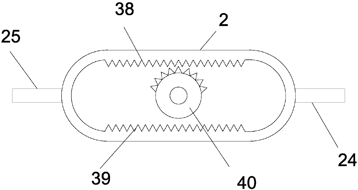
[0020] see Figure 1-4 , a double-sided high-efficiency grinding device for dust-reducing steel plates, including an operating room 1, wherein a driven shaft 20 is vertically rotated in the operating room 1, and a driven pulley 22 and a driving bevel gear are arranged on the driven shaft 20 21. In the operating room 1, there is a horizontal rotation shaft 18, and the left end of the rotating shaft 18 is coaxially fixed with a driven bevel gear 19 meshed with the driving bevel gear 21; There is an extension plate 17 extending to the left, and the bottom surface of the extension plate 17 is fixed with a driving motor 5 upside down. A drive belt 23 is wound around the driven pulley 22; a grinding plate 3 is fixedly mounted on the bottom end of the drive shaft 4; The first spur rack 38 and the second spur rack 39 are parallel to each other, and the bottom o...


PUM


Abstract

The invention discloses a dust reduction type steel plate double-face efficient polishing device which comprises an operation chamber. A driven shaft is vertically and rotationally arranged in the operation chamber, and a polishing plate is coaxially and fixedly installed at the bottom end of a driving shaft; a guide rod connected with the left side wall of the operation chamber in a sliding manner is horizontally arranged at the left end of a dual-rectangle-shaped frame, and a sliding rod movably connected with a vertical plate is horizontally arranged at the right end of a support; and a limiting spring is arranged on the sliding rod on the vertical plate at the right end of the upper surface of a bearing table in a sleeving manner, a positioning disc is fixedly installed on the right side of the vertical plate at the right end, a center hole is formed in the center of the positioning disc, and an upper positioning hole and a lower positioning hole which are subject to up-and-down vertical symmetry with respect to the center of the center hole are formed in the positioning disc. The dust reduction type steel plate double-face efficient polishing device is ingenious in structure and reasonable in design; the polishing plate is driven by a driving motor to achieve rotary polishing on a steel plate, the polishing scope is wider, and the steel plate polishing efficiency is improved; and the sliding rod is rotated to drive an L-shaped positioning shaft to rotate, and therefore double-face polishing on the steel plate can be achieved, and the overturning operation is easy and convneient.

Description

technical field [0001] The invention relates to the technical field of steel plate grinding, in particular to a double-sided high-efficiency grinding device for dust-reducing steel plates. Background technique [0002] The steel plate is a flat steel material that is poured with molten steel and pressed after cooling. Steel plates are classified according to thickness, thin steel plates < 4 mm and the thinnest 0.2 mm, thick steel plates 4-60 mm, and extra-thick steel plates 60-115 mm. Steel plates are divided into hot-rolled and cold-rolled according to rolling. [0003] In the mechanical processing industry, it is necessary to polish and derust the surface of the steel plate before stamping and cutting the steel plate to make parts, so as to remove the rust stains and burrs on the surface of the steel plate and ensure the smooth surface of the steel plate. The existing steel plate grinding The grinding effect of the device on the steel plate is not good, and the grindi...

Claims


Application Information

Patent Timeline
IPC IPC(8): B24B7/00B24B7/02B24B55/06
CPCB24B7/00B24B7/02B24B55/06Y02P70/10
Inventor 张梦雪
Owner ZHENGZHOU UNIV
Learn More